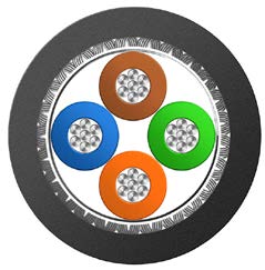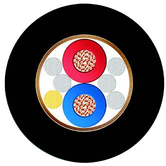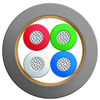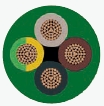
This fire-resistant cable is strictly designed in accordance with the BS EN 50525-3-31 standard, integrating multiple safety properties such as circuit integrity, flame retardancy, halogen-free, low smoke, and non-corrosive into one. It is specifically designed for construction, industrial, transportation, and other scenarios with stringent fire safety requirements, ensuring continuous circuit operation in extreme environments such as fires to protect life and property safety.This fire-resistant cable is strictly designed in accordance with the BS EN 50525-3-31 standard, integrating multiple safety properties including circuit integrity, flame retardancy, halogen-free, low smoke, and non-corrosive into one. Specifically engineered for construction, industrial, transportation, and other scenarios with stringent fire safety requirements, it ensures continuous circuit operation in extreme environments such as fires, thereby protecting life and property safety.
Basic design adapted from BS EN 50525-3-31
| Circuit Integrity | IEC 60331-21; BS 6387 |
| Flame Retardance (Single vertical wire or cable test) | IEC 60332-1-2; EN 60332-1-2 |
| Reduced fire Propagation (Vertically-mounted bundled wires & cables test) | IEC 60332-3-24; EN 60332-3-24 |
| Halogen free | IEC 60754-1; EN 50267-2-1 |
| No Corrosive Gas Emission | IEC60754-2; EN 50267-2-2 |
| Minimum Smoke Emission | IEC 61034-2; EN 61034-2 |
300/500V
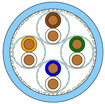
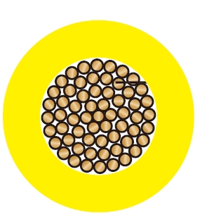
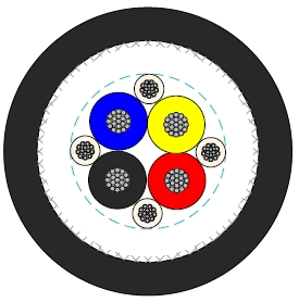
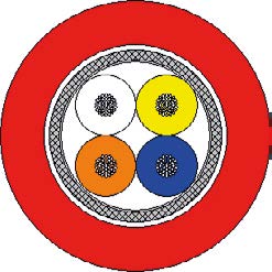
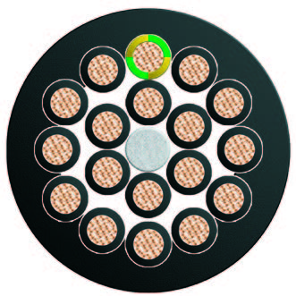
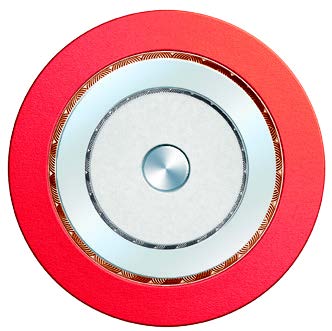
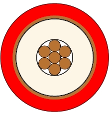
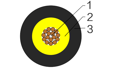
ConductorCopper conductor according to BS EN 60228 class 1/2/5.
Fire BarrierMica glass tape.
InsulationThermoplastic compound of type TI 7 to EN 50363-7.
Insulation OptionUV resistance, hydrocarbon resistance, oil resistance, water resistance, anti-rodent and anti-termite properties can be offered as option.
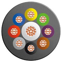
Black, Blue, Brown, Grey, Orange, Pink, Red, Turquoise, Violet, White, Green and Yellow. Bi-colours of any combination of the above mono-colours are permitted.
Maximum temperature range during operation70°C
Maximum short circuit temperature (5 Seconds)160°C
Minimum bending radius4 x Overall Diameter
| Conductor | FRP300 mZ1-U/R/K | ||||
|---|---|---|---|---|---|
| No. of Cores × Cross-sectional Area | Conductor Class | Nominal Insulation Thickness | Min. Overall Diameter | Max. Overall Diameter | Approx. Weight |
| No.×mm² | mm | mm | mm | kg/km | |
| 1×0.5 | 1 | 0.6 | 2.9 | 3.3 | 13.5 |
| 1×0.75 | 1 | 0.6 | 3.1 | 3.5 | 16.5 |
| 1×1.0 | 1 | 0.6 | 3.2 | 3.7 | 19.7 |
| 1×0.5 | 2 | 0.6 | 3.0 | 3.4 | 14.4 |
| 1×0.75 | 2 | 0.6 | 3.2 | 3.6 | 17.3 |
| 1×1.0 | 2 | 0.6 | 3.3 | 3.8 | 21.3 |
| 1×0.5 | 5 | 0.6 | 3.1 | 3.5 | 14.2 |
| 1×0.75 | 5 | 0.6 | 3.2 | 3.7 | 17.7 |
| 1×1.0 | 5 | 0.6 | 3.4 | 3.8 | 20.7 |
Conductor operating temperature70°C
Ambient temperature30°C
| Conductor cross-sectional area | Single-phase a.c. | Three-phase a.c. |
|---|---|---|
| mm² | A | A |
| 0.5 | 3 | 3 |
| 0.75 | 6 | 6 |
| 1.0 | 10 | 10 |
Note: These values apply to the majority of cases. further information should be sought in unusual cases eg.: When high ambient temperatures are involved, ie. above 30°C Where long lengths are used Where ventilation is restricted Where the cords are used for other purposes, ego internal wiring of apparatus. | ||
| Conductor cross-sectional area | 2 cables d.c. | 2 cables, single-phase a.c. | 3 or 4 cables, three-phase a.c. | |||||
|---|---|---|---|---|---|---|---|---|
| Ref. Methods A&B (enclosed in conduit or trunking) | Ref. Methods C, F&G (clipped direct, on trays or in free air) | Ref. Methods A&B (enclosed in conduit or trunking) | Ref. Methods C, F&G (clipped direct, on trays or in free air) | |||||
| Cables touching | Cables spaced* | Cables touching, Trefoil | Cables touching, flat | Cables spaced*, flat | ||||
| 1 | 2 | 3 | 4 | 5 | 6 | 7 | 8 | 9 |
| mm² | mV/A/m | mV/A/m | mV/A/m | mV/A/m | mV/A/m | mV/A/m | mV/A/m | mV/A/m |
| 0.5 | 93 | 93 | 93 | 93 | 80 | 80 | 80 | 80 |
| 0.75 | 62 | 62 | 62 | 62 | 54 | 54 | 54 | 54 |
| 1.0 | 46 | 46 | 46 | 46 | 40 | 40 | 40 | 40 |
Note: *Spacings larger than one cable diameter will result in a large voltage drop.