APPLICATION
The cables are mainly used in power stations, mass transit underground passenger systems, airports, petrochemical plants, hotels, hospitals, and high-rise buildings.
STANDARDS
Basic design to BS 6004: 2012
FIRE PERFORMANCE
| Flame Retardance (Single Vertical Wire Test) | EN 60332-1-2 |
VOLTAGE RATING
300/500V
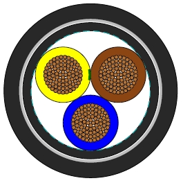
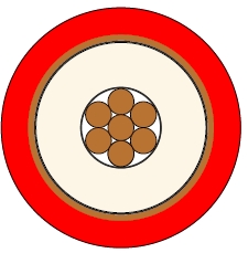
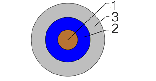
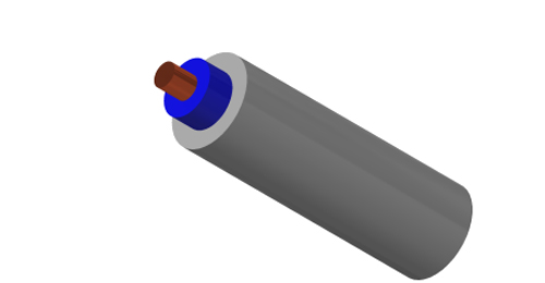
CABLE CONSTRUCTION
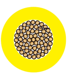
| Conductor | Annealed copper conductor, class 1 (1.0mm² to 2.5mm²) or class 2 (4mm² to 35mm²) according to BS EN 60228. |
| Insulation | PVC Type TI 1 according to BS EN 50363-3. |
| Outer Sheath | PVC Type 6 according to BS 7655-4.2. |
| Outer Sheath Option | UV resistance, hydrocarbon resistance, oil resistance, anti rodent and anti termite properties can be offered as option. Compliance to fire performance standard (IEC 60332-1, IEC 60332-3, UL 1581, UL 1666 etc) depends on the oxygen index of the PVC compound and the overall cable design. LSPVC can also be provided upon request. |
COLOUR CODE
| Insulation Colour | Brown or blue. |
| Sheath Colour | Grey, other colours can be offered upon request. |
PHYSICAL AND THERMAL PROPERTIES
| Maximum temperature range during operation (PVC) | 70°C |
| Maximum short circuit temperature (5 Seconds) | 160°C |
| Minimum bending radius | Up to 10mm² - Fixed: 3 x overall diameter |
| 10mm² to 25mm² - Fixed: 4 x overall diameter |
CONSTRUCTION PARAMETERS
| Conductor | FLP300 VV-U/R |
|---|
| No. of Cores x Cross Section | Class of Conductor | Nominal Insulation Thickness | Nominal Sheath Thickness | Maximum Overall Diameter | Approx. Weight |
|---|
| No.xmm² | | mm | | mm | kg/km |
|---|
| 1x1.0 | 1 | 0.6 | 0.8 | 4.5 | 27 |
| 1x1.5 | 1 | 0.7 | 0.8 | 5.0 | 36 |
| 1x2.5 | 1 | 0.8 | 0.8 | 5.7 | 52 |
| 1x4.0 | 2 | 0.8 | 0.9 | 6.7 | 76 |
| 1x6.0 | 2 | 0.8 | 0.9 | 7.3 | 100 |
| 1x10 | 2 | 1.0 | 0.9 | 8.8 | 160 |
| 1x16 | 2 | 1.0 | 1.0 | 10.1 | 230 |
| 1x25 | 2 | 1.2 | 1.1 | 12.1 | 340 |
| 1x35 | 2 | 1.2 | 1.1 | 13.5 | 440 |
ELECTRICAL PROPERTIES
| Conductor Operating Temperature | 70°C |
| Ambient Temperature | 30° |
Current-Carrying Capacities (Amp) according to BS 7671:2008 table 4D1A
| Conductor cross- sectional area | Reference Method A (enclosed in conduit in thermally insulating wall etc) | Reference Method B (enclosed in conduit on a wall or in trunking etc) | Reference Method C (clipped direct) | Reference Method F (in free air or on a perforated cable tray horizontal or vertical etc) |
|---|
| Touching | Spaced by one cable diameter |
|---|
| 2 cables, single-phase a.c. or d.c. | 3 or 4 cables, three-phase a.c. | 2 cables, single-phase a.c. or d.c | 3 or 4 cables, three-phase a.c. | 2 cables, single-phase a.c. or d.c. flat and touching | 3 or 4 cables, three-phase a.c. flat and touching or trefoil | 2 cables, single-phase a.c. or d.c. flat | 3 cables, three-phase a.c. flat | 3 cables, three-phase a.c. trefoil | 2 cables, single-phase a.c. or d.c. or 3 cables three-phase a.c. flat |
|---|
| Horizontal | Vertical |
|---|
| 1 | 2 | 3 | 4 | 5 | 6 | 7 | 8 | 9 | 10 | 11 | 12 |
|---|
| mm² | A | A | A | A | A | A | A | A | A | A | A |
|---|
| 1.0 | 11.0 | 10.5 | 13.5 | 12.0 | 15.5 | 14 | - | - | - | - | - |
| 1.5 | 14.5 | 13.5 | 17.5 | 15.5 | 20 | 18 | - | - | - | - | - |
| 2.5 | 20 | 18 | 24 | 21 | 27 | 25 | - | - | - | - | - |
| 4.0 | 26 | 24 | 32 | 28 | 37 | 33 | - | - | - | - | - |
| 6.0 | 34 | 31 | 41 | 36 | 47 | 43 | - | - | - | - | - |
| 10 | 46 | 42 | 57 | 50 | 65 | 59 | - | - | - | - | - |
| 16 | 61 | 56 | 76 | 68 | 87 | 79 | - | - | - | - | - |
| 25 | 80 | 73 | 101 | 89 | 114 | 104 | 131 | 114 | 110 | 146 | 130 |
| 35 | 99 | 89 | 125 | 110 | 141 | 129 | 162 | 143 | 137 | 181 | 162 |
Voltage Drop (Per Amp Per Meter) according to BS 7671:2008 table 4D1B
| Nominal Cross Section Area | 2 cables d.c. | 2 cables, single-phase a.c. | 3 or 4 cables, three-phase a.c. |
|---|
| Ref. Methods A and B (enclosed in conduit or trunking) | Ref. Methods C & F(clipped direct, on trays or in free air) | Ref. Methods A & B (enclosed in conduit or trunking | Ref. Methods C & F (clipped direct, on trays or in free air) |
|---|
| Cables touching | Cables spaced* | Cables touching, Trefoil | Cables touching, Flat | Cables spaced*, Flat |
|---|
| 1 | 2 | 3 | 4 | 5 | 6 | 7 | 8 | 9 |
|---|
| mm² | mV/A/m | mV/A/m | mV/A/m | mV/A/m | mV/A/m | mV/A/m | mV/A/m | mV/A/m |
|---|
| 1.0 | 44 | 44 | 44 | 44 | 38 | 38 | 38 | 38 |
| 1.5 | 29 | 29 | 29 | 29 | 25 | 25 | 25 | 25 |
| 2.5 | 18 | 18 | 18 | 18 | 15 | 15 | 15 | 15 |
| 4.0 | 11 | 11 | 11 | 11 | 9.5 | 9.5 | 9,5 | 9.5 |
| 6.0 | 7.3 | 7.3 | 7.3 | 7.3 | 6.4 | 6.4 | 6.4 | 6.4 |
| 10 | 4.4 | 4.4 | 4.4 | 4.4 | 3.8 | 3.8 | 3.8 | 3.8 |
| 16 | 2.8 | 2.8 | 2.8 | 2.8 | 2.4 | 2.4 | 2.4 | 2.4 |
|
| r | x | z | r | x | z | r | x | z | r | x | z | r | x | z | r | x | z | r | x | z |
| 25 | 1.75 | 1.8 | 0.33 | 1.8 | 1.75 | 0.20 | 1.75 | 1.75 | 0.29 | 1.8 | 1.5 | 0.29 | 1.55 | 1.5 | 0.175 | 1.5 | 1.5 | 0.25 | 1.55 | 1.5 | 0.32 | 1.55 |
| 35 | 1.25 | 1.3 | 0.31 | 1.3 | 1.25 | 0.195 | 1.25 | 1.25 | 0.28 | 1.3 | 1.1 | 0.27 | 1.10 | 1.1 | 0.170 | 1.1 | 1.1 | 0.24 | 1.10 | 1.1 | 0.32 | 1.15 |
Note: *Spacings larger than one cable diameter will result in a large voltage drop.
r = conductor resistance at operating temperature
x = reactance
z = impedance