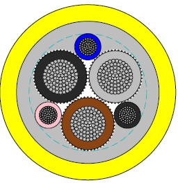
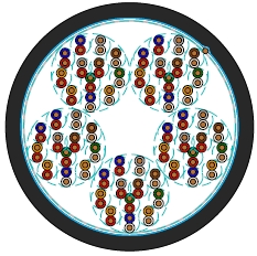
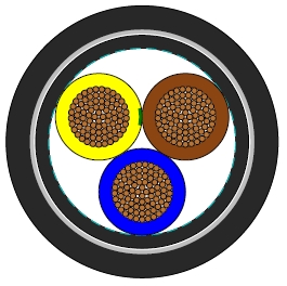
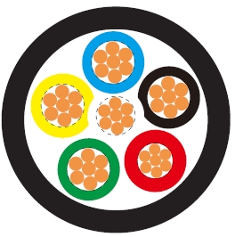
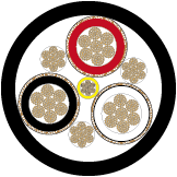
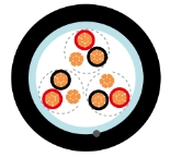
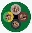
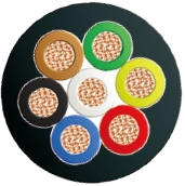
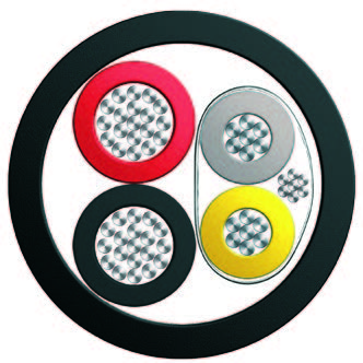
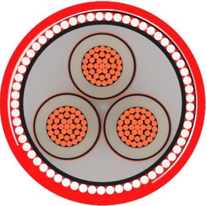
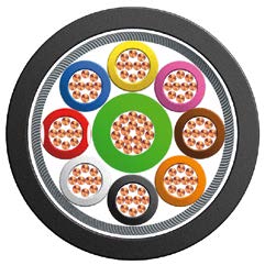
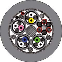
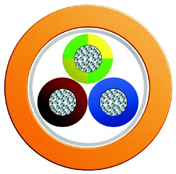
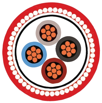
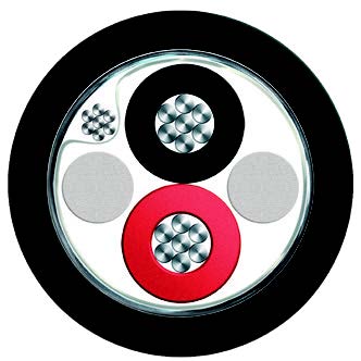
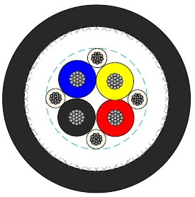
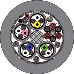
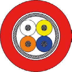
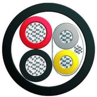
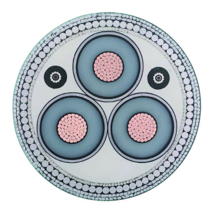
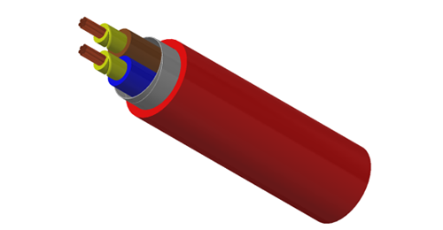
For industrial instrumentation circuits requiring individual screening of each signal pair as well as an overall screen. The unarmoured construction combines mica glass tape, XLPE insulation and an LSZH outer sheath for indoor equipment and instrument interconnections, including damp locations.
Basic design to BS EN 50288-7 (formerly BS 5308)
| Circuit Integrity | IEC 60331-21; BS 6387 CWZ (Optional); BS EN 50200 (PH30/PH60/PH120) |
|---|---|
| Flame Retardance (Single Vertical Wire or cable test) | IEC 60332-1-2; EN 60332-1-2 |
| Reduced Fire Propagation (Vertically-mounted bundled wires & cables test) | IEC 60332-3-24; EN 60332-3-24 |
| Halogen Free | IEC 60754-1; EN 50267-2-1 |
| No Corrosive Gas Emission | IEC 60754-2; EN 50267-2-2 |
| Minimum Smoke Emission | IEC 61034-2; EN 61034-2 |
300, 500V
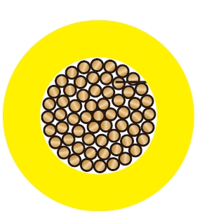
| Conductor | Plain or metal coated copper wire, solid, stranded or flexible according to IEC 60228 class 1, 2 and class 5. |
| Fire Barrier | Mica glass tape. |
| Insulation | Extruded XLPE compound according to EN 50290-2-29. LSZH, PE, PP compound can be offered as options. |
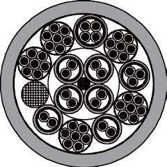
| Pairs | Two insulated conductors uniformly twisted together with a lay not exceeding 100mm (≤1.5mm²) or 150mm (for 2.5mm²). |
| Individual Screen | Aluminium/polyester tape is applied over each pair with metallic side down in contact with tinned copper drain wire, 0.5mm². |
| Binder Tape | PETP transparent tape. |
| Overall Screen | Aluminium/polyester tape is applied over the laid up cores with metallic side down in contact with tinned copper drain wire, 0.5mm². Copper braid screen or aluminium/polyester tape combination with copper braid screen can be offered as option. |
| Outer Sheath | Thermoplastic LSZH compound type LTS3 as per BS 7655-6.1 (Thermosetting LSZH compound type SW2-SW4 as per BS 7655-2.6 can be offered). |
| Outer Sheath Option | UV resistance, hydrocarbon resistance, oil resistance, anti-rodent and anti-termite properties can be offered as option. |
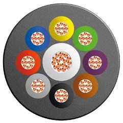
| Insulation Colour | Colours and/or additional ring markings and/or symbols achieved by the use of coloured insulation or by a coloured surface using extrusion, printing or painting. |
| Outer Sheath | Black. Other colours can be offered upon request. |
| Temperature range during operation | -30°C - +90°C |
| Temperature range fixed installation | -5°C - +50°C |
| Maximum short circuit temperature (5 Seconds) | 250°C |
| Minimum bending radius | 7.5 x Overall Diameter |
| Conductor area size | mm² | 0.5 | 0.75 | 1.0 | 1.5 | |
|---|---|---|---|---|---|---|
| Insulation thickness (Nominal) | mm | 0.4 | 0.4 | 0.4 | 0.5 | |
| Insulation thickness (Minimum) | mm | 0.26 | 0.26 | 0.26 | 0.35 | |
| Conductor resistance (20°C) | ohm/km | 36.7 | 25.0 | 18.5 | 12.3 | |
| Minimum Insulation resistance (20°C) | Mohm/km | 1000 | ||||
| Maximum Mutual capacitance | nf/km | 250 | ||||
| Capacitance Unbalance | pf/500m | 500 | ||||
| Maximum l/R (ratio) | μH/Ω | 25 | 25 | 25 | 40 | |
| Operating Voltage | V | 300 | ||||
| Dielectric strength for 1 minute | AC | V | ≥1000 | |||
| DC | V | ≥2000 | ||||
| Conductor area size | mm² | 0.5 | 0.75 | 1.0 | 1.5 | 2.5 | |
|---|---|---|---|---|---|---|---|
| Insulation thickness (nominal) | mm | 0.6 | 0.6 | 0.6 | 0.6 | 0.7 | |
| Insulation thickness (minimum) | mm | 0.44 | 0.44 | 0.44 | 0.44 | 0.53 | |
| Conductor resistance (20°C) | ohm/km | 36.7 | 25.0 | 18.5 | 12.3 | 7.4 | |
| Minimum Insulation resistance (20°C) | Mohm/km | 1000 | |||||
| Maximum Mutual capacitance | nf/km | 250 | |||||
| Capacitance Unbalance | pf/500m | 500 | |||||
| Maximum l/R (ratio) | μH/Ω | 25 | 25 | 25 | 40 | 60 | |
| Operating Voltage | V | 500 | |||||
| Dielectric strength for 1 minute | AC | V | ≥2000 | ||||
| DC | V | ≥3000 | |||||
| Conductor | RE-2X(St)H PiMF...CI | ||||
|---|---|---|---|---|---|
| No. of Pairs X Cross Section | Class of Conductor | Nominal Insulation Thickness | Nominal Outer Sheath Thickness | Approx. Overall Diameter | Approx. Weight |
| mm² | mm | mm | mm | kg/km | |
| 0.5mm² | |||||
| 2x2x0.5 | 2 | 0.4 | 1.0 | 12.0 | 138 |
| 3x2x0.5 | 2 | 0.4 | 1.0 | 12.7 | 173 |
| 4x2x0.5 | 2 | 0.4 | 1.1 | 14.2 | 222 |
| 5x2x0.5 | 2 | 0.4 | 1.1 | 15.6 | 263 |
| 8x2x0.5 | 2 | 0.4 | 1.1 | 18.5 | 377 |
| 10x2x0.5 | 2 | 0.4 | 1.2 | 22.2 | 478 |
| 12x2x0.5 | 2 | 0.4 | 1.2 | 23.0 | 545 |
| 16x2x0.5 | 2 | 0.4 | 1.3 | 25.8 | 705 |
| 20x2x0.5 | 2 | 0.4 | 1.4 | 28.2 | 865 |
| 24x2x0.5 | 2 | 0.4 | 1.5 | 32.5 | 1046 |
| 0.75mm² | |||||
| 2x2x0.75 | 2 | 0.4 | 1.0 | 12.6 | 155 |
| 3x2x0.75 | 2 | 0.4 | 1.1 | 13.6 | 206 |
| 4x2x0.75 | 2 | 0.4 | 1.1 | 15.0 | 253 |
| 5x2x0.75 | 2 | 0.4 | 1.2 | 16.7 | 312 |
| 8x2x0.75 | 2 | 0.4 | 1.2 | 19.8 | 449 |
| 10x2x0.75 | 2 | 0.4 | 1.3 | 23.6 | 567 |
| 12x2x0.75 | 2 | 0.4 | 1.3 | 24.4 | 648 |
| 16x2x0.75 | 2 | 0.4 | 1.4 | 27.5 | 839 |
| 20x2x0.75 | 2 | 0.4 | 1.5 | 30.0 | 1028 |
| 24x2x0.75 | 2 | 0.4 | 1.5 | 34.5 | 1221 |
| 1.0mm² | |||||
| 2x2x1.0 | 2 | 0.4 | 1.0 | 13.4 | 177 |
| 3x2x1.0 | 2 | 0.4 | 1.1 | 14.4 | 238 |
| 4x2x1.0 | 2 | 0.4 | 1.2 | 16.1 | 304 |
| 5x2x1.0 | 2 | 0.4 | 1.2 | 17.7 | 363 |
| 8x2x1.0 | 2 | 0.4 | 1.2 | 21.0 | 528 |
| 10x2x1.0 | 2 | 0.4 | 1.3 | 25.1 | 667 |
| 12x2x1.0 | 2 | 0.4 | 1.4 | 26.2 | 782 |
| 16x2x1.0 | 2 | 0.4 | 1.5 | 29.4 | 1012 |
| 20x2x1.0 | 2 | 0.4 | 1.5 | 32.0 | 1220 |
| 24x2x1.0 | 2 | 0.4 | 1.6 | 36.9 | 1473 |
| 1.5mm² | |||||
| 2x2x1.5 | 2 | 0.5 | 1.1 | 15.2 | 230 |
| 3x2x1.5 | 2 | 0.5 | 1.2 | 16.4 | 309 |
| 4x2x1.5 | 2 | 0.5 | 1.2 | 18.1 | 384 |
| 5x2x1.5 | 2 | 0.5 | 1.3 | 20.1 | 472 |
| 8x2x1.5 | 2 | 0.5 | 1.3 | 24.0 | 690 |
| 10x2x1.5 | 2 | 0.5 | 1.4 | 28.7 | 870 |
| 12x2x1.5 | 2 | 0.5 | 1.5 | 29.9 | 1021 |
| 16x2x1.5 | 2 | 0.5 | 1.6 | 33.6 | 1323 |
| 20x2x1.5 | 2 | 0.5 | 1.7 | 36.7 | 1622 |
| 24x2x1.5 | 2 | 0.5 | 1.8 | 42.3 | 1955 |
| Conductor | RE-2X(St)H PiMF...CI | ||||
|---|---|---|---|---|---|
| No. of Pairs X Cross Section | Class of Conductor | Nominal Insulation Thickness | Nominal Outer Sheath Thickness | Approx. Overall Diameter | Approx. Weight |
| mm² | mm | mm | mm | kg/km | |
| 0.5mm² | |||||
| 2x2x0.5 | 2 | 0.6 | 1.0 | 13.4 | 157 |
| 3x2x0.5 | 2 | 0.6 | 1.1 | 14.5 | 208 |
| 4x2x0.5 | 2 | 0.6 | 1.1 | 15.9 | 254 |
| 5x2x0.5 | 2 | 0.6 | 1.2 | 17.7 | 313 |
| 8x2x0.5 | 2 | 0.6 | 1.2 | 21.1 | 447 |
| 10x2x0.5 | 2 | 0.6 | 1.3 | 25.2 | 565 |
| 12x2x0.5 | 2 | 0.6 | 1.4 | 26.3 | 660 |
| 16x2x0.5 | 2 | 0.6 | 1.5 | 29.5 | 850 |
| 20x2x0.5 | 2 | 0.6 | 1.5 | 32.1 | 1018 |
| 24x2x0.5 | 2 | 0.6 | 1.6 | 37.0 | 1230 |
| 0.75mm² | |||||
| 2x2x0.75 | 2 | 0.6 | 1.1 | 14.2 | 184 |
| 3x2x0.75 | 2 | 0.6 | 1.1 | 15.2 | 233 |
| 4x2x0.75 | 2 | 0.6 | 1.2 | 16.9 | 297 |
| 5x2x0.75 | 2 | 0.6 | 1.2 | 18.6 | 353 |
| 8x2x0.75 | 2 | 0.6 | 1.3 | 22.3 | 523 |
| 10x2x0.75 | 2 | 0.6 | 1.4 | 26.7 | 660 |
| 12x2x0.75 | 2 | 0.6 | 1.4 | 27.6 | 754 |
| 16x2x0.75 | 2 | 0.6 | 1.5 | 31.0 | 972 |
| 20x2x0.75 | 2 | 0.6 | 1.6 | 33.9 | 1190 |
| 24x2x0.75 | 2 | 0.6 | 1.7 | 39.1 | 1436 |
| 1.0mm² | |||||
| 2x2x1.0 | 2 | 0.6 | 1.1 | 15.0 | 207 |
| 3x2x1.0 | 2 | 0.6 | 1.2 | 16.2 | 276 |
| 4x2x1.0 | 2 | 0.6 | 1.2 | 17.8 | 340 |
| 5x2x1.0 | 2 | 0.6 | 1.3 | 19.8 | 418 |
| 8x2x1.0 | 2 | 0.6 | 1.3 | 23.6 | 605 |
| 10x2x1.0 | 2 | 0.6 | 1.4 | 28.2 | 764 |
| 12x2x1.0 | 2 | 0.6 | 1.5 | 29.3 | 893 |
| 16x2x1.0 | 2 | 0.6 | 1.6 | 33.0 | 1153 |
| 20x2x1.0 | 2 | 0.6 | 1.7 | 36.0 | 1411 |
| 24x2x1.0 | 2 | 0.6 | 1.8 | 41.6 | 1701 |
| 1.5mm² | |||||
| 2x2x1.5 | 2 | 0.6 | 1.1 | 16.0 | 241 |
| 3x2x1.5 | 2 | 0.6 | 1.2 | 17.2 | 324 |
| 4x2x1.5 | 2 | 0.6 | 1.3 | 19.2 | 414 |
| 5x2x1.5 | 2 | 0.6 | 1.3 | 21.1 | 496 |
| 8x2x1.5 | 2 | 0.6 | 1.4 | 25.4 | 740 |
| 10x2x1.5 | 2 | 0.6 | 1.5 | 30.3 | 932 |
| 12x2x1.5 | 2 | 0.6 | 1.6 | 31.5 | 1091 |
| 16x2x1.5 | 2 | 0.6 | 1.7 | 35.4 | 1410 |
| 20x2x1.5 | 2 | 0.6 | 1.8 | 38.7 | 1727 |
| 24x2x1.5 | 2 | 0.6 | 1.9 | 44.7 | 2080 |
| 2.5mm² | |||||
| 2x2x2.5 | 2 | 0.7 | 1.2 | 18.4 | 324 |
| 3x2x2.5 | 2 | 0.7 | 1.3 | 19.8 | 439 |
| 4x2x2.5 | 2 | 0.7 | 1.4 | 22.0 | 563 |
| 5x2x2.5 | 2 | 0.7 | 1.5 | 24.5 | 691 |
| 8x2x2.5 | 2 | 0.7 | 1.6 | 29.4 | 1033 |
| 10x2x2.5 | 2 | 0.7 | 1.7 | 35.1 | 1298 |
| 12x2x2.5 | 2 | 0.7 | 1.8 | 36.5 | 1519 |
| 16x2x2.5 | 2 | 0.7 | 1.9 | 41.0 | 1965 |
| 20x2x2.5 | 2 | 0.7 | 2.1 | 45.0 | 2434 |
| 24x2x2.5 | 2 | 0.7 | 2.2 | 51.9 | 2927 |
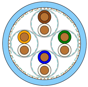
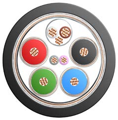
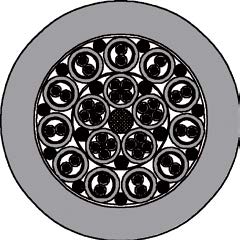
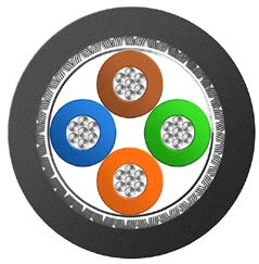
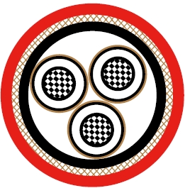
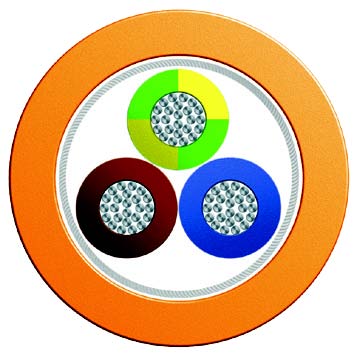
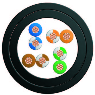
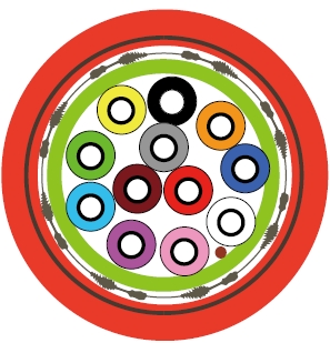
Individual aluminium/polyester screens around each twisted pair.
A further overall foil screen surrounds the laid-up assembly.
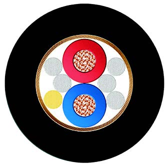
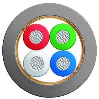
Mica glass tape fire barrier, XLPE insulation and LSZH outer sheath.
Specify pair count, conductor area, conductor class and the 300V or 500V version. Plan individual and overall screen terminations to suit the connected equipment.
Fire Resistant Multipair Instrumentation Cable, Overall Screened
Fire Resistant Multipair Instrumentation Cable, Individual/Overall Screened, SWA
Multipair Instrumentation Cable, Individual and Overall Screened, XLPE/PVC
Each pair has its own foil screen, and a second foil screen encloses the complete pair assembly.
The individual and overall screens use 0.5 mm² tinned copper drain wires.
This version is unarmoured; the related SWA version adds galvanised steel wire armour.
Mica glass tape provides the fire barrier and XLPE is the standard insulation.
The minimum bending radius is 7.5 times the overall cable diameter.