The unarmoured XLPE versions are generally used for indoor installation and suitable for wet and damp areas. Generally used within industrial process manufacturing plants for communication, data and voice transmission signals and services.
Basic design to BS EN 50288-7 (formerly BS 5308)
Flame Retardance (Single Vertical Wire Test) :BS EN 60332-1-2
300V, 500V
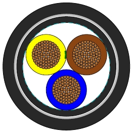
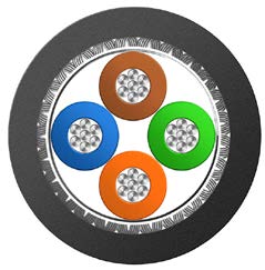
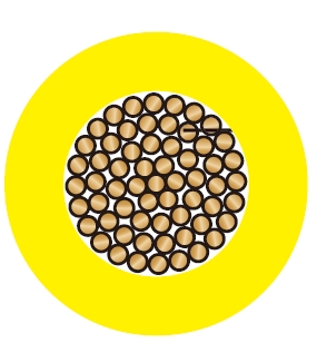
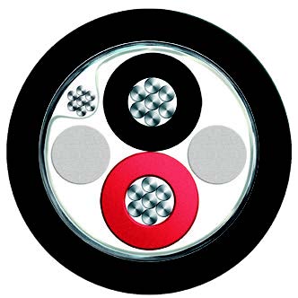
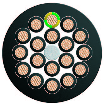
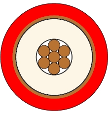
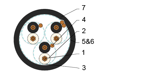
Conductor : Plain or metal coated copper wire, solid, stranded or flexible according to IEC 60228 class 1, 2 and 5.
Insulation : Extruded XLPE compound according to EN 50290-2-29. PVC, PE, PP compound can be offered as options.
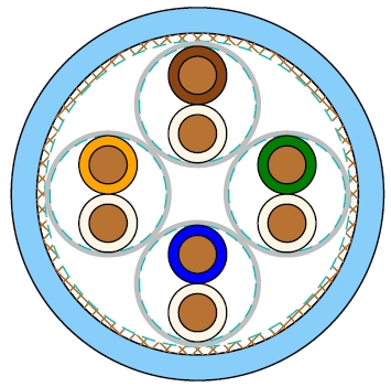
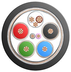
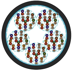
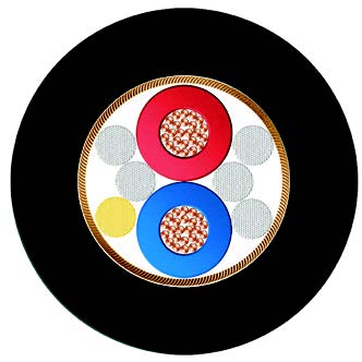
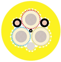
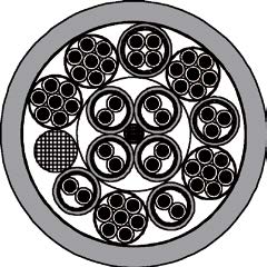
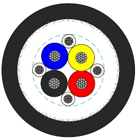
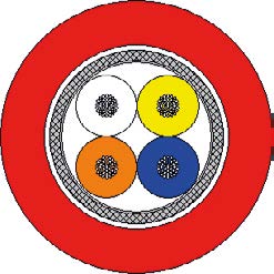
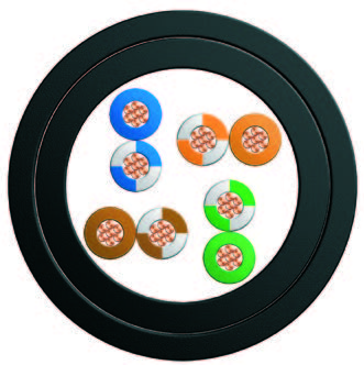
Pairs : Two insulated conductors uniformly twisted together with a lay not exceeding 100mm (≤1.5mm²) or 150mm (for 2.5mm²).
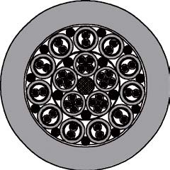
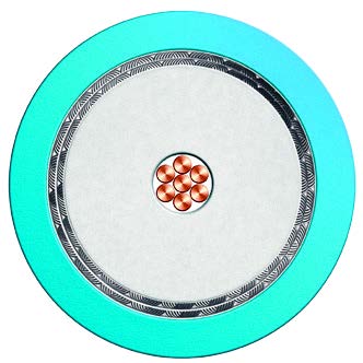
Individual Screen : Aluminium/polyester tape is applied over each pair with metallic side down in contact with tinned copper drain wire, 0.5mm².
Binder Tape : PETP transparent tape.
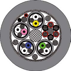
Overall Screen : Aluminium/polyester tape is applied over the laid up cores with metallic side down in contact with tinned copper drain wire, 0.5mm². Copper braid screen or aluminium/polyester tape combination with copper braid screen can be offered as option.
Outer Sheath : Thermoplastic PVC compound according to EN 50290-2-22.
Outer Sheath Option : UV resistance, hydrocarbon resistance, oil resistance, anti-rodent and anti-termite properties can be offered as option. Compliance to fire performance standard (IEC 60332-1, IEC 60332-3, UL 1581, UL 1666 etc) depends on the oxygen index of the PVC compound and the overall cable design. LSPVC can also be provided upon request.
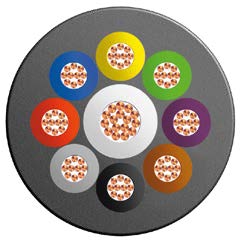
Insulation Colour : Colours and/or additional ring markings and/or symbols achieved by the use of coloured insulation or by a coloured surface using extrusion, printing or painting.
Outer Sheath : Black. Other colours can be offered upon request.
Temperature range during operation : -30°C - +90°C
Temperature range fixed installation : -5°C - +50°C
Maximum short circuit temperature (5 Seconds) : 250°C
Minimum bending radius : 7.5 x Overall Diameter
| Conductor Area Size | mm² | 0.5 | 0.75 | 1.0 | 1.5 |
| Insulation Thickness (nominal) | mm | 0.4 | 0.4 | 0.4 | 0.5 |
| Insulation Thickness (minimum) | mm | 0.26 | 0.26 | 0.26 | 0.35 |
| Conductor Resistance (20°C) | ohm/km | 36.7 | 25.0 | 18.5 | 12.3 |
| Minimum Insulation Resistance (20°C) | Mohm/km | 1000 | |||
| Maximum Mutual Capacitance | nf/km | 250 | |||
| Capacitance Unbalance | pf/500m | 500 | |||
| Maximum L/R (ratio) | μH/Ω | 25 | 25 | 25 | 40 |
| Operating Voltage | V | 300 | |||
| Dielectric Strength for 1 Minute | AC | V | ≥1000 | ||
| DC | V | ≥2000 | |||
| Conductor Area Size | mm² | 0.5 | 0.75 | 1.0 | 1.5 | 2.5 |
| Insulation Thickness (nominal) | mm | 0.6 | 0.6 | 0.6 | 0.6 | 0.7 |
| Insulation Thickness (minimum) | mm | 0.44 | 0.44 | 0.44 | 0.44 | 0.53 |
| Conductor resistance (20°C) | ohm/km | 36.7 | 25.0 | 18.5 | 12.3 | 7.4 |
| Minimum Insulation Resistance (20°C) | Mohm/km | 1000 | ||||
| Maximum Mutual Capacitance | nf/km | 250 | ||||
| Capacitance Unbalance | pf/500m | 500 | ||||
| Maximum L/R (ratio) | μH/Ω | 25 | 25 | 25 | 40 | 60 |
| Operating Voltage | V | 500 | ||||
| Dielectric Strength for 1 Minute | AC | V | ≥2000 | |||
| DC | V | ≥3000 | ||||
| Conductor | RE-2X(St)Y PiMF | ||||
|---|---|---|---|---|---|
| No. of Pairs X Cross Section | Class of Conductor | Nominal Insulation Thickness | Nominal Outer Sheath Thickness | Approx. Overall Diameter | Approx. Weight |
| mm² | mm | mm | mm | kg/km | |
| 0.5mm² | |||||
| 2x2x0.5 | 2 | 0.4 | 1.0 | 8.6 | 85 |
| 3x2x0.5 | 2 | 0.4 | 1.0 | 9.0 | 109 |
| 4x2x0.5 | 2 | 0.4 | 1.1 | 10.1 | 139 |
| 5x2x0.5 | 2 | 0.4 | 1.1 | 11.0 | 165 |
| 8x2x0.5 | 2 | 0.4 | 1.1 | 12.9 | 238 |
| 10x2x0.5 | 2 | 0.4 | 1.2 | 15.3 | 301 |
| 12x2x0.5 | 2 | 0.4 | 1.2 | 15.8 | 345 |
| 16x2x0.5 | 2 | 0.4 | 1.3 | 17.7 | 448 |
| 20x2x0.5 | 2 | 0.4 | 1.4 | 19.4 | 550 |
| 24x2x0.5 | 2 | 0.4 | 1.5 | 22.3 | 664 |
| 0.75mm² | |||||
| 2x2x0.75 | 2 | 0.4 | 1.0 | 9.2 | 100 |
| 3x2x0.75 | 2 | 0.4 | 1.1 | 9.9 | 135 |
| 4x2x0.75 | 2 | 0.4 | 1.1 | 10.8 | 167 |
| 5x2x0.75 | 2 | 0.4 | 1.2 | 12.0 | 205 |
| 8x2x0.75 | 2 | 0.4 | 1.2 | 14.1 | 298 |
| 10x2x0.75 | 2 | 0.4 | 1.3 | 16.8 | 375 |
| 12x2x0.75 | 2 | 0.4 | 1.3 | 17.3 | 432 |
| 16x2x0.75 | 2 | 0.4 | 1.4 | 19.4 | 560 |
| 20x2x0.75 | 2 | 0.4 | 1.5 | 21.2 | 688 |
| 24x2x0.75 | 2 | 0.4 | 1.5 | 24.2 | 817 |
| 1.0mm² | |||||
| 2x2x1.0 | 2 | 0.4 | 1.0 | 9.9 | 120 |
| 3x2x1.0 | 2 | 0.4 | 1.1 | 10.7 | 163 |
| 4x2x1.0 | 2 | 0.4 | 1.2 | 12.0 | 209 |
| 5x2x1.0 | 2 | 0.4 | 1.2 | 13.1 | 251 |
| 8x2x1.0 | 2 | 0.4 | 1.2 | 15.4 | 369 |
| 10x2x1.0 | 2 | 0.4 | 1.3 | 18.3 | 464 |
| 12x2x1.0 | 2 | 0.4 | 1.4 | 19.1 | 546 |
| 16x2x1.0 | 2 | 0.4 | 1.5 | 21.4 | 709 |
| 20x2x1.0 | 2 | 0.4 | 1.5 | 23.2 | 860 |
| 24x2x1.0 | 2 | 0.4 | 1.6 | 26.6 | 1037 |
| 1.5mm² | |||||
| 2x2x1.5 | 2 | 0.5 | 1.1 | 11.8 | 164 |
| 3x2x1.5 | 2 | 0.5 | 1.2 | 12.7 | 223 |
| 4x2x1.5 | 2 | 0.5 | 1.2 | 14.0 | 279 |
| 5x2x1.5 | 2 | 0.5 | 1.3 | 15.5 | 344 |
| 8x2x1.5 | 2 | 0.5 | 1.3 | 18.3 | 508 |
| 10x2x1.5 | 2 | 0.5 | 1.4 | 21.8 | 639 |
| 12x2x1.5 | 2 | 0.5 | 1.5 | 22.8 | 752 |
| 16x2x1.5 | 2 | 0.5 | 1.6 | 25.5 | 978 |
| 20x2x1.5 | 2 | 0.5 | 1.7 | 27.9 | 1202 |
| 24x2x1.5 | 2 | 0.5 | 1.8 | 32.1 | 1447 |
| Conductor | RE-2X(St)Y PiMF | ||||
|---|---|---|---|---|---|
| No. of Pairs X Cross Section | Class of Conductor | Nominal Insulation Thickness | Nominal Outer Sheath Thickness | Approx. Overall Diameter | Approx. Weight |
| mm² | mm | mm | mm | kg/km | |
| 0.5mm² | |||||
| 2x2x0.5 | 2 | 0.6 | 1.0 | 10.0 | 101 |
| 3x2x0.5 | 2 | 0.6 | 1.1 | 10.8 | 133 |
| 4x2x0.5 | 2 | 0.6 | 1.1 | 11.8 | 164 |
| 5x2x0.5 | 2 | 0.6 | 1.2 | 13.1 | 201 |
| 8x2x0.5 | 2 | 0.6 | 1.2 | 15.4 | 289 |
| 10x2x0.5 | 2 | 0.6 | 1.3 | 18.4 | 365 |
| 12x2x0.5 | 2 | 0.6 | 1.4 | 19.2 | 427 |
| 16x2x0.5 | 2 | 0.6 | 1.5 | 21.5 | 550 |
| 20x2x0.5 | 2 | 0.6 | 1.5 | 23.3 | 661 |
| 24x2x0.5 | 2 | 0.6 | 1.6 | 26.7 | 798 |
| 0.75mm² | |||||
| 2x2x0.75 | 2 | 0.6 | 1.1 | 10.8 | 122 |
| 3x2x0.75 | 2 | 0.6 | 1.1 | 11.5 | 156 |
| 4x2x0.75 | 2 | 0.6 | 1.2 | 12.8 | 199 |
| 5x2x0.75 | 2 | 0.6 | 1.2 | 14.0 | 237 |
| 8x2x0.75 | 2 | 0.6 | 1.3 | 16.7 | 353 |
| 10x2x0.75 | 2 | 0.6 | 1.4 | 19.8 | 444 |
| 12x2x0.75 | 2 | 0.6 | 1.4 | 20.5 | 509 |
| 16x2x0.75 | 2 | 0.6 | 1.5 | 23.0 | 659 |
| 20x2x0.75 | 2 | 0.6 | 1.6 | 25.1 | 807 |
| 24x2x0.75 | 2 | 0.6 | 1.7 | 28.9 | 973 |
| 1.0mm² | |||||
| 2x2x1.0 | 2 | 0.6 | 1.1 | 11.6 | 143 |
| 3x2x1.0 | 2 | 0.6 | 1.2 | 12.5 | 191 |
| 4x2x1.0 | 2 | 0.6 | 1.2 | 13.7 | 238 |
| 5x2x1.0 | 2 | 0.6 | 1.3 | 15.2 | 292 |
| 8x2x1.0 | 2 | 0.6 | 1.3 | 17.9 | 427 |
| 10x2x1.0 | 2 | 0.6 | 1.4 | 21.3 | 537 |
| 12x2x1.0 | 2 | 0.6 | 1.5 | 22.2 | 630 |
| 16x2x1.0 | 2 | 0.6 | 1.6 | 25.0 | 816 |
| 20x2x1.0 | 2 | 0.6 | 1.7 | 27.2 | 1000 |
| 24x2x1.0 | 2 | 0.6 | 1.8 | 31.3 | 1204 |
| 1.5mm² | |||||
| 2x2x1.5 | 2 | 0.6 | 1.1 | 12.5 | 173 |
| 3x2x1.5 | 2 | 0.6 | 1.2 | 13.5 | 235 |
| 4x2x1.5 | 2 | 0.6 | 1.3 | 15.0 | 302 |
| 5x2x1.5 | 2 | 0.6 | 1.3 | 16.5 | 362 |
| 8x2x1.5 | 2 | 0.6 | 1.4 | 19.7 | 545 |
| 10x2x1.5 | 2 | 0.6 | 1.5 | 23.5 | 685 |
| 12x2x1.5 | 2 | 0.6 | 1.6 | 24.4 | 804 |
| 16x2x1.5 | 2 | 0.6 | 1.7 | 27.4 | 1043 |
| 20x2x1.5 | 2 | 0.6 | 1.8 | 29.9 | 1281 |
| 24x2x1.5 | 2 | 0.6 | 1.9 | 34.4 | 1541 |
| 2.5mm² | |||||
| 2x2x2.5 | 2 | 0.7 | 1.2 | 14.9 | 245 |
| 3x2x2.5 | 2 | 0.7 | 1.3 | 16.1 | 335 |
| 4x2x2.5 | 2 | 0.7 | 1.4 | 17.9 | 432 |
| 5x2x2.5 | 2 | 0.7 | 1.5 | 19.9 | 531 |
| 8x2x2.5 | 2 | 0.7 | 1.6 | 23.8 | 801 |
| 10x2x2.5 | 2 | 0.7 | 1.7 | 28.3 | 1005 |
| 12x2x2.5 | 2 | 0.7 | 1.8 | 29.4 | 1180 |
| 16x2x2.5 | 2 | 0.7 | 1.9 | 33.0 | 1533 |
| 20x2x2.5 | 2 | 0.7 | 2.1 | 36.2 | 1901 |
| 24x2x2.5 | 2 | 0.7 | 2.2 | 41.6 | 2284 |