High-performance Cable Products: The Perfect Combination of Excellent Design and Safety Assurance
Our cable products are high-performance cables designed and manufactured in strict accordance with international standards. With their outstanding fireproof performance, stable electrical characteristics, and diverse application adaptability, they are the ideal choice for various electrical systems.
Basic design adapted from BS 7211:2012
| Circuit Integrity | IEC 60331-21; BS 6387 |
| Flame Retardance (Single vertical wire or cable test) | IEC 60332-1-2; EN 60332-1-2 |
| Reduced Fire Propagation (Vertically-mounted bundled wires & cables test) | IEC 60332-3-24; EN 60332-3-24 |
| Halogen free | IEC 60754-1; EN 50267-2-1 |
| No Corrosive Gas Emission | IEC60754-2; EN 50267-2-2 |
| Minimum Smoke Emission | IEC 61034-2; EN 61034-2 |
450/750V
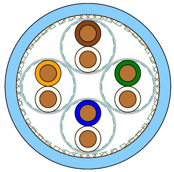
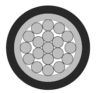
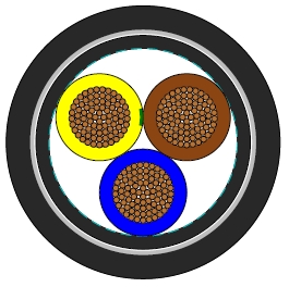
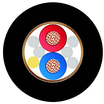
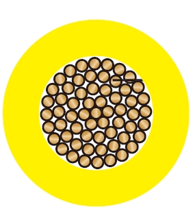
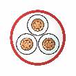
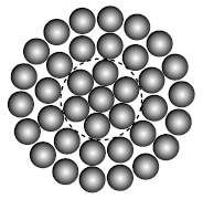
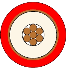
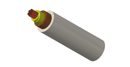
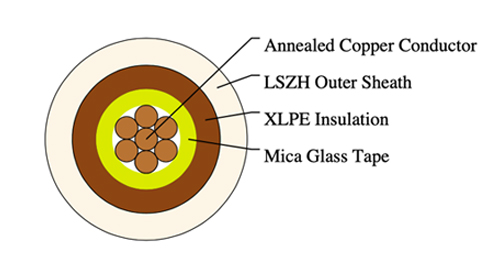
Conductor : Annealed copper conductor, solid or stranded according to BS EN 60228 class 1 or class 2.
Fire Barrier : Mica glass tape.
Insulation : XLPE type GP 8 according to BS 7655-1.3. Crosslinked polyolefin material type EI 5 according to EN 50363-5 can be offered as option.
CPC (Circuit Protective Conductor) : Uninsulated copper conductor.
Outer Sheath : Extruded LSZH type LTS 4 according to BS 7655-6.1.
Outer Sheath Option : UV resistance, hydrocarbon resistance, oil resistance, anti-rodent and anti-termite properties can be offered as option.
Insulation Colour : Brown or blue.
Sheath Colour: White; other colours can be offered upon request.
Maximum temperature range during operation : 90°C
Maximum short circuit temperature (5 Seconds) : 250°C
Minimum bending radius :
OD<8mm : 4 × Overall Diameter
8mm≤OD≤12mm : 5 × Overall Diameter
OD>12mm : 6 × Overall Diameter
| Conductor | FRP450-mRZ1-U/R | |||||
|---|---|---|---|---|---|---|
| No. of Cores × Cross-sectional Area | Conductor Class | Nominal Insulation Thickness | Nominal Sheath Thickness | Min. Overall Diameter | Max. Overall Diameter | Approx. Weight |
| No.×mm² | mm | mm | mm | mm | kg/km | |
| 1×1.0 | 1 | 0.7 | 0.8 | 4.9 | 5.8 | 30 |
| 1×1.5 | 1 | 0.7 | 0.8 | 5.2 | 6.0 | 38 |
| 1×2.5 | 1 | 0.7 | 0.8 | 5.6 | 6.5 | 51 |
| 1×4 | 1 | 0.7 | 0.8 | 6.2 | 7.3 | 70 |
| 1×6 | 1 | 0.7 | 0.8 | 6.7 | 7.8 | 95 |
| 1×1.0 | 2 | 0.7 | 0.8 | 5.0 | 5.9 | 35 |
| 1×1.5 | 2 | 0.7 | 0.8 | 5.3 | 6.2 | 43 |
| 1×2.5 | 2 | 0.7 | 0.8 | 5.7 | 6.6 | 56 |
| 1×4 | 2 | 0.7 | 0.9 | 6.3 | 7.4 | 77 |
| 1×6 | 2 | 0.7 | 0.9 | 6.9 | 8.1 | 104 |
| 1×10 | 2 | 0.7 | 0.9 | 7.7 | 9.1 | 147 |
| 1×16 | 2 | 0.7 | 0.9 | 8.6 | 10.2 | 211 |
| 1×25 | 2 | 0.9 | 1.0 | 10.4 | 12.4 | 325 |
| 1×35 | 2 | 0.9 | 1.1 | 11.6 | 13.8 | 489 |
Conductor operating temperature : 90°C
Ambient temperature : 30°C
| Conductor cross-sectional area | Ref. Method A (enclosed in conduit in thermally insulating wall etc.) | Ref. Method B (enclosed in conduit on a wall or in trunking etc.) | Ref. Method C (clipped direct) | Ref. Method F (in free air or on a perforated cable tray, horizontal or vertical etc) Touching | Ref. Method G (in free air) Spaced by one cable diameter | ||||||
|---|---|---|---|---|---|---|---|---|---|---|---|
| 2 cables, single-phase a.c. or d.c. | 3 or 4 cables, three-phase a.c. | 2 cables, single-phase a.c. or d.c | 3 or 4 cables, three-phase a.c. | 2 cables, single-phase a.c. or d.c. flat and touching | 3 or 4 cables, three-phase a.c. flat and touching or trefoil | 2 cables, single-phase a.c. or d.c. flat | 3 cables, three-phase a.c. flat | 3 cables, three-phase a.c. trefoil | 2 cables, single-phase a.c. or d.c. or 3 cables three-phase a.c. flat | ||
| Horizontal | Vertical | ||||||||||
| 1 | 2 | 3 | 4 | 5 | 6 | 7 | 8 | 9 | 10 | 11 | 12 |
| mm² | A | A | A | A | A | A | A | A | A | A | A |
| 1.0 | 14 | 13 | 17 | 15 | 19 | 17.5 | - | - | - | - | - |
| 1.5 | 19 | 17 | 23 | 20 | 25 | 23 | - | - | - | - | - |
| 2.5 | 26 | 23 | 31 | 28 | 34 | 31 | - | - | - | - | - |
| 4 | 35 | 31 | 42 | 37 | 46 | 41 | - | - | - | - | - |
| 6 | 45 | 40 | 54 | 48 | 59 | 54 | - | - | - | - | - |
| 10 | 61 | 54 | 75 | 66 | 81 | 74 | - | - | - | - | - |
| 16 | 81 | 73 | 100 | 88 | 109 | 99 | - | - | - | - | - |
| 25 | 106 | 95 | 133 | 117 | 143 | 130 | 161 | 141 | 135 | 182 | 161 |
| 35 | 131 | 117 | 164 | 144 | 176 | 161 | 200 | 176 | 169 | 226 | 201 |
| Conductor cross-sectional area | 2 cables d.c. | 2 cables, single-phase a.c. | 3 or 4 cables, three-phase a.c. | |||||||||||||||||||
|---|---|---|---|---|---|---|---|---|---|---|---|---|---|---|---|---|---|---|---|---|---|---|
| Ref. Methods A&B (enclosed in conduit or trunking) | Ref. Methods C, F&G (clipped direct, on trays or in free air) | Ref. Methods A&B (enclosed in conduit or trunking) | Ref. Methods C, F&G (clipped direct, on trays or in free air) | |||||||||||||||||||
| Cables touching | Cables spaced* | Cables touching, Trefoil | Cables touching, flat | Cables spaced*, flat | ||||||||||||||||||
| 1 | 2 | 3 | 4 | 5 | 6 | 7 | 8 | 9 | ||||||||||||||
| mm² | mV/A/m | mV/A/m | mV/A/m | mV/A/m | mV/A/m | mV/A/m | mV/A/m | mV/A/m | ||||||||||||||
| 1.0 | 46 | 46 | 46 | 46 | 40 | 40 | 40 | 40 | ||||||||||||||
| 1.5 | 31 | 31 | 31 | 31 | 27 | 27 | 27 | 27 | ||||||||||||||
| 2.5 | 19 | 19 | 19 | 19 | 16 | 16 | 16 | 16 | ||||||||||||||
| 4 | 12 | 12 | 12 | 12 | 10 | 10 | 10 | 10 | ||||||||||||||
| 6 | 7.9 | 7.9 | 7.9 | 7.9 | 6.8 | 6.8 | 6.8 | 6.8 | ||||||||||||||
| 10 | 4.7 | 4.7 | 4.7 | 4.7 | 4.0 | 4.0 | 4.0 | 4.0 | ||||||||||||||
| 16 | 2.9 | 2.9 | 2.9 | 2.9 | 2.5 | 2.5 | 2.5 | 2.5 | ||||||||||||||
| r | x | z | r | x | z | r | x | z | r | x | z | r | x | z | r | x | z | r | x | z | ||
| 25 | 1.85 | 1.85 | 0.31 | 1.90 | 1.85 | 0.190 | 1.85 | 1.85 | 0.28 | 1.85 | 1.60 | 0.27 | 1.65 | 1.60 | 0.165 | 1.60 | 1.60 | 0.190 | 1.60 | 1.60 | 0.27 | 1.65 |
| 35 | 1.35 | 1.35 | 0.29 | 1.35 | 1.35 | 0.180 | 1.35 | 1.35 | 0.27 | 1.35 | 1.15 | 0.25 | 1.15 | 1.15 | 0.155 | 1.15 | 1.15 | 0.180 | 1.15 | 1.15 | 0.26 | 1.20 |
Note: *Spacings larger than one cable diameter will result in a large voltage drop.
r = conductor resistance at operating temperature
x = reactance
z = impedance