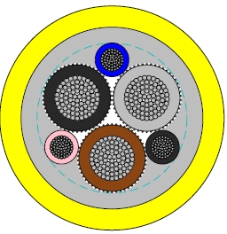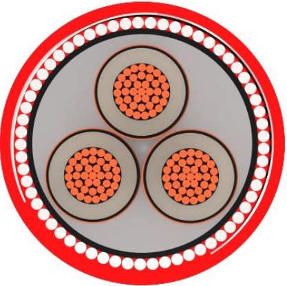
This P19/P19/P21 RFOU 12/20kV medium-voltage power cable features a flame-retardant, low-smoke, zero-halogen design and excellent mud resistance. It is specifically engineered for fixed installations in marine engineering and offshore oil platforms. Whether in harsh marine environments or industrial settings with stringent safety requirements, it ensures safe and reliable power transmission. Suitable for trunk and branch lines of various medium-voltage power systems, it provides stable and dependable power supply to critical equipment. Choose the P19/P19/P21 RFOU cable to safeguard your marine engineering projects.
IEC 60092-353
IEC 60092-351
IEC 60092-359
IEC 60332-1
IEC 60332-3-22
IEC 60754-1,2
IEC 61034-1,2
NEK 606:2004
Electrical Characteristics
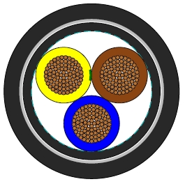
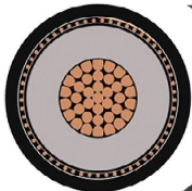
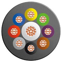
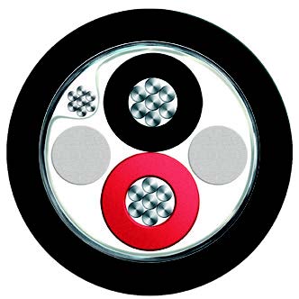
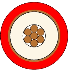
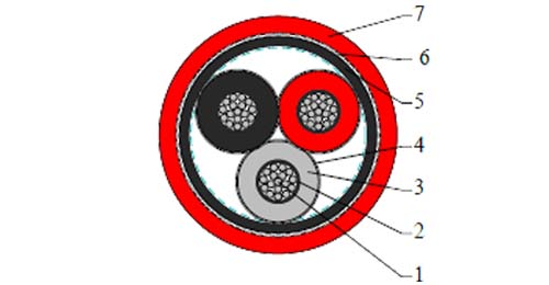
| Conductors | Circular tinned annealed stranded copper to IEC 60228 class 2. |
| Conductor Screen | Semi conducting material. |
| Insulation | Halogen-free EPR. XLPE can be offered as an option (for TFOU cable). |
| Insulation Screen | Semi conducting material and tinned copper wire braid. |
| Bedding | Halogen free compound. |
| Armour | Tinned copper wire braid. |
| Outer Sheath | Halogen free thermosetting compound, SHF2 (for TYPE P19) |
| or halogen free mud resistant thermosetting compound, SHF MUD (for TYPE P19/P21), coloured red. |
| Nominal Cross Section Area | mm^2 | 16 | 25 | 35 | 50 | 70 | 95 |
| Nominal Conductor Diameter | mm | 5.2 | 6.5 | 7.4 | 8.7 | 10.3 | 12.2 |
| Maximum DC Resistant@20℃ | Ω/km | 1.16 | 0.734 | 0.529 | 0.391 | 0.27 | 0.195 |
| Continuous Current Rating@45℃1 Core | A | 96 | 127 | 157 | 196 | 242 | 293 |
| Continuous Current Rating@45℃3 Core | A | 67 | 89 | 110 | 137 | 169 | 205 |
| Short Circuit Current 1s | A | 2290 | 3580 | 5010 | 7150 | 10020 | 13590 |
| Operating Voltage | KV | 12/20 | 12/20 | 12/20 | 12/20 | 12/20 | 12/20 |
| Nominal Cross Section Area | mm^2 | 120 | 150 | 185 | 240 | 300 |
| Nominal Conductor Diameter | mm | 13.8 | 15.1 | 17.0 | 19.6 | 21.9 |
| Maximum DC Resistant@20℃ | Ω/km | 0.154 | 0.126 | 0.1 | 0.0762 | 0.0607 |
| Continuous Current Rating@45℃1 Core | A | 339 | 389 | 444 | 522 | 601 |
| Continuous Current Rating@45℃3 Core | A | 237 | 272 | 311 | 365 | 421 |
| Short Circuit Current 1s | A | 17170 | 21460 | 26470 | 34340 | 42930 |
| Operating Voltage | KV | 12/20 | 12/20 | 12/20 | 12/20 | 12/20 |
| Ambient Temperature Correction Factors | 35 | 40 | 45 | 50 | 55 | 60 | 65 | 70 | 75 | 80 |
| Rating Factor | 1.1 | 1.05 | 1.0 | 0.94 | 0.88 | 0.82 | 0.74 | 0.67 | 0.58 | 0.47 |
| Bending Radius | 15×OD (during installation) |
| 9×OD (fixed installed) | |
| Temperature Range | -20℃ ~ +90℃ |
| Construction No. of cores×Cross section(mm^2) | Nominal Insulation Thickness (mm) | Nominal Sheath Thickness (mm) | Nominal Overall Diameter (mm) | Nominal Weight (kg/km) | |
| Inner | Outer | ||||
| 1×16 | 5.5 | 1.0 | 1.6 | 28 | 1200 |
| 1×25 | 5.5 | 1.0 | 1.7 | 31.6 | 1530 |
| 1×35 | 5.5 | 1.2 | 1.8 | 32.3 | 1595 |
| 1×50 | 5.5 | 1.2 | 2.0 | 33.8 | 1795 |
| 1×70 | 5.5 | 1.2 | 2.1 | 34.6 | 2070 |
| 1×95 | 5.5 | 1.2 | 2.1 | 37.0 | 2470 |
| 1×120 | 5.5 | 1.3 | 2.1 | 38.8 | 2810 |
| 1×150 | 5.5 | 1.3 | 2.2 | 40.7 | 3245 |
| 1×185 | 5.5 | 1.4 | 2.2 | 42.9 | 3765 |
| 1×240 | 5.5 | 1.4 | 2.4 | 45.8 | 4510 |
| 1×300 | 5.5 | 1.4 | 2.6 | 48.5 | 5315 |
| 3×16 | 5.5 | 1.4 | 2.6 | 55.5 | 4950 |
| 3×25 | 5.5 | 1.4 | 2.7 | 62.2 | 5705 |
| 3×35 | 5.5 | 1.4 | 2.8 | 62.6 | 5990 |
| 3×50 | 5.5 | 1.8 | 3.0 | 65.4 | 6740 |
| 3×70 | 5.5 | 1.8 | 3.1 | 69.1 | 7790 |
| 3×95 | 5.5 | 2.0 | 3.3 | 73.0 | 9150 |
| 3×120 | 5.5 | 2.0 | 3.4 | 77.4 | 10580 |
| 3×150 | 5.5 | 2.0 | 3.5 | 81.9 | 12145 |
| 3×185 | 5.5 | 2.0 | 3.7 | 89.5 | 12265 |
| 3×240 | 5.5 | 2.2 | 3.9 | 96.1 | 14725 |
| 3×300 | 5.5 | 2.2 | 4.0 | 101.9 | 17190 |