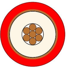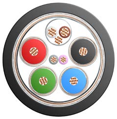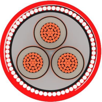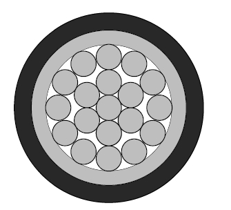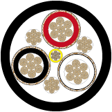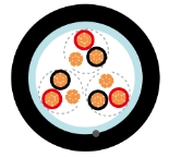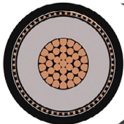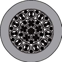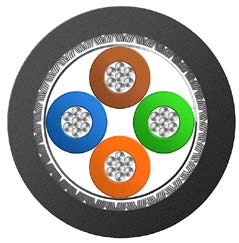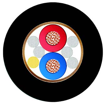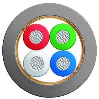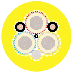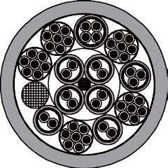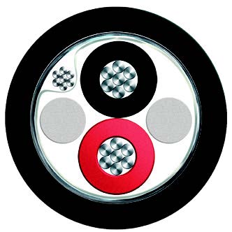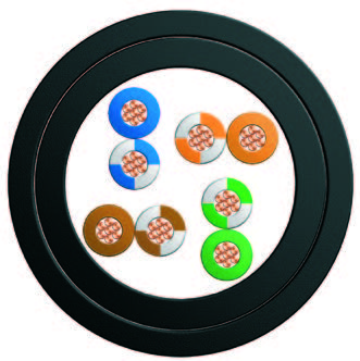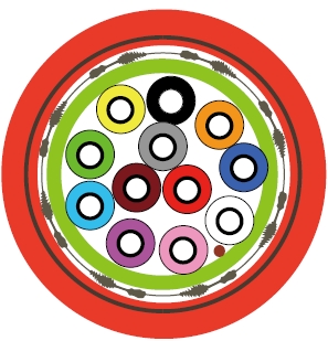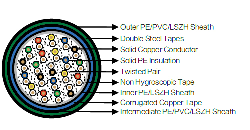
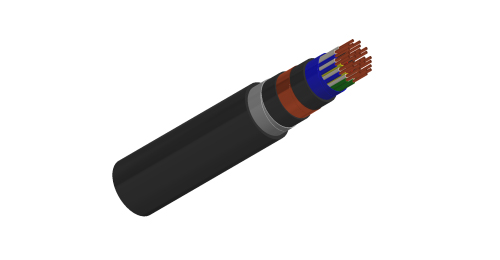
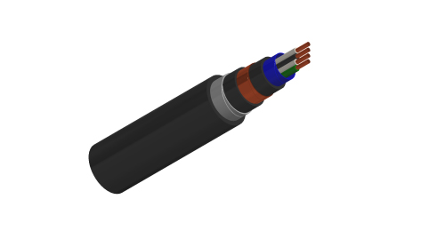
ZPAU and ZPAU-SH cables carry signalling circuits between control centres and trackside equipment shelters on AC-electrified railway routes. PE-insulated solid copper conductors are twisted into pairs. A corrugated copper tape screen, intermediate sheath and double steel tapes form the layered screening construction. The range includes ZPAU PE/PVC sheath arrangements and the ZPAU-SH LSZH option. The railway traction voltage and the signalling cable operating voltage are separate design quantities.
SNCF CT 445 / SNCT ST 698G
NF F 55-698
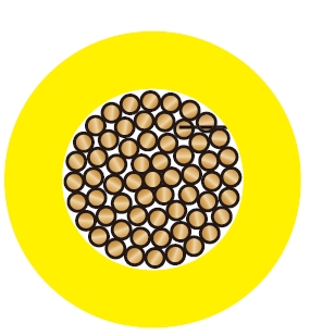
Conductors : Solid annealed copper, 1.0/1.5 mm² nominal cross section area.
Insulation : Solid polyethylene.
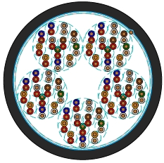
Cabling Element : Each two conductors are twisted together to form a pair.
Stranding : Pairs are helically stranded in layers to form the cable core.
Core Wrapping : Plastic tape(s) with overlapping.
Inner Sheath : PE sheath. LSZH FR option can be offered upon request to NF C 32 070.2.2 (C1).
Electrostatic Shield : One corrugated copper tape.
Intermediate Sheath : PE/PVC sheath. LSZH FR option can be offered upon request to NF C 32 070.2.2 (C1).
Electromagnetic Shield : Two helically applied steel tapes of 0.5mm.
Outer Sheath : PE/PVC Sheath. LSZH FR option can be offered upon request to NF C 32 070.2.2 (C1).
Remarks : ZPAU : PE/PVC Sheath; ZPAU-SH : LSZH Sheath.
| Nominal Conductor Diameter | mm | 1.13 | 1.38 |
| Nominal Cross Section Area | mm² | 1.0 | 1.5 |
| Maximum Conductor Resistance (DC) | Ω/km | 18.1 | 12.31 |
| Minimum Insulation Resistance @500 V DC (3mins) | MΩ.km | 5000 | 5000 |
| Maximum Mutual Capacitance @1000Hz (AC) | nF/km | 55 | 55 |
| Maximum Capacitance Unbalance (pair to pair) @800Hz | |||
| 100% cases | pF/500 m | 400 | 400 |
| 90% cases | pF/500 m | 200 | 200 |
| Attenuation @45KHz | dB/km | 2.5 | 2.5 |
| Characteristic Impedance @45KHz | Ω | 120 | 120 |
| Dielectric Strength, conductor to conductor (DC voltage 3secs) | V | 4500 | 4500 |
| Operating Voltage (AC/DC) | V | 450/750 | 450/750 |
| Peak Value (AC) | V | 900 | 900 |
Minimum Bending Radius : 8×OD (static) ; 16×OD (dynamic)
Temperature Range : -40℃ to +70℃ (during operation) ; -20℃ to +50℃ (during installation)
| Inductive Voltage (V/km) Em | 28 | 32 | 37 | 42 | 47 | 50 | 70 | 80 | 100 | 120 | 170 | 225 |
| Reduction Factor @50Hz Rk | 0.75 | 0.70 | 0.60 | 0.50 | 0.40 | 0.35 | 0.30 | 0.28 | 0.26 | 0.25 | 0.24 | 0.25 |
| Cable Code | No. of Pairs | Nominal Sheath Thickness | Nominal Overall Diameter | Nominal Weight | ||
|---|---|---|---|---|---|---|
| Inner | Interm. | Outer | ||||
| mm | mm | mm | mm | kg/km | ||
| 1.13mm Conductor, 2.3mm Insulated Wire | ||||||
| BRAIL ZPAU-2Y2Y(K)2YB2Y-1P1S | 1 | 1.0 | 0.8 | 1.6 | 16.2 | 490 |
| BRAIL ZPAU-2Y2Y(K)2YB2Y-2P1S | 2 | 1.0 | 0.8 | 1.6 | 17.0 | 550 |
| BRAIL ZPAU-2Y2Y(K)2YB2Y-3P1S | 3 | 1.0 | 0.8 | 1.6 | 22.2 | 820 |
| BRAIL ZPAU-2Y2Y(K)2YB2Y-4P1S | 4 | 1.0 | 0.8 | 1.6 | 23.8 | 890 |
| BRAIL ZPAU-2Y2Y(K)2YB2Y-7P1S | 7 | 1.0 | 0.8 | 1.7 | 26.7 | 1080 |
| BRAIL ZPAU-2Y2Y(K)2YB2Y-14P1S | 14 | 1.2 | 0.8 | 1.8 | 32.3 | 1560 |
| BRAIL ZPAU-2Y2Y(K)2YB2Y-21P1S | 21 | 1.2 | 1.1 | 2.0 | 37.2 | 1990 |
| BRAIL ZPAU-2Y2Y(K)2YB2Y-28P1S | 28 | 1.2 | 1.1 | 2.2 | 41.4 | 2380 |
| BRAIL ZPAU-2Y2Y(K)2YB2Y-56P1S | 56 | 1.3 | 1.3 | 2.5 | 52.9 | 3700 |
| 1.38mm Conductor, 2.55mm Insulated Wire | ||||||
| BRAIL ZPAU-2Y2Y(K)2YB2Y-14P1.5S | 14 | 1.2 | 0.8 | 1.8 | 35.0 | 2050 |
| BRAIL ZPAU-2Y2Y(K)2YB2Y-21P1.5S | 21 | 1.2 | 1.1 | 2.0 | 39.5 | 2525 |
Solid copper conductors in 1.0 and 1.5 mm² constructions.
Twisted pairs with corrugated copper tape and double steel tape layers.
A reduction-factor table at 50 Hz supports project-specific induction assessment.
Specify pair count, conductor size and complete sheath arrangement. Assess induction using the values at the relevant field strength, together with the route geometry and bonding design. The electrical table lists operating voltage as 450/750 V AC/DC; a reference to a 25 kV railway describes the traction system. Include the selected cable diameter and installation temperature in route planning.
ZCO3 & ZCO3-SH Quad Railway Signalling Cable for High-Speed Lines
ZPGU Screened Local Railway Signalling Cable, 1.0 mm² Copper Pairs
What does the SH suffix identify?
ZPAU-SH identifies the LSZH sheath option. Specify the complete sheath arrangement and required fire-performance documentation.
Does use beside a 25 kV railway give the cable a 25 kV rating?
No. The traction-system voltage describes the railway environment. This cable’s operating-voltage entry is 450/750 V AC/DC.
What are the principal metallic layers?
The construction includes a corrugated copper tape electrostatic screen and two helically applied steel tapes.
Is the reduction factor constant?
It varies with the stated inductive voltage. Use the 50 Hz table for the relevant assessment conditions.
Which cable details should a procurement schedule include?
Specify ZPAU or ZPAU-SH, pair count, conductor cross-section, sheath arrangement, lengths and the required project documentation.