


The cables are designed for remote control and teletransmission in underground railway networks. The cables can be laid in channel, cable tray, or on hook supports, along suburban railway lines electrifi ed at maximum 1500V DC.
AFNOR NF F 55-624
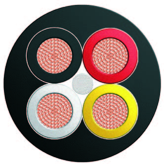
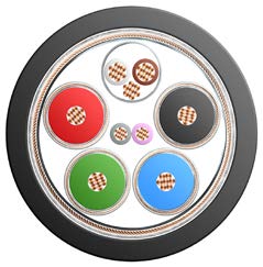
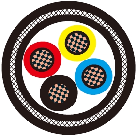
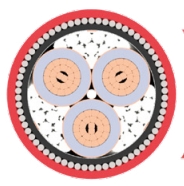
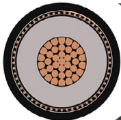
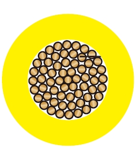
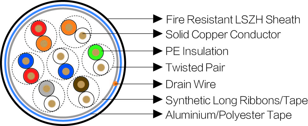
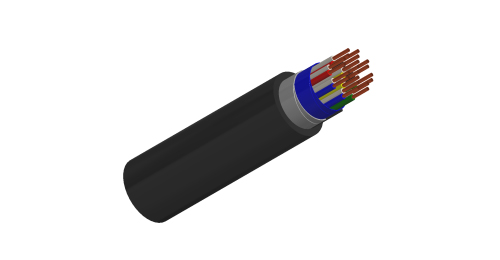
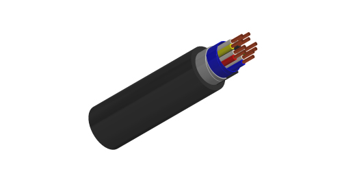
Electrical Characteristics at 20℃Conductors: Solid copper conductor, 0.5/0.6/0.9 mm nominal diameter.
Insulation: Polyethylene insulation.
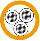
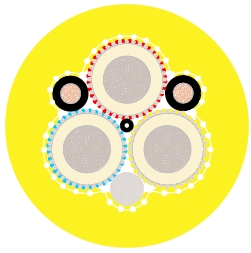
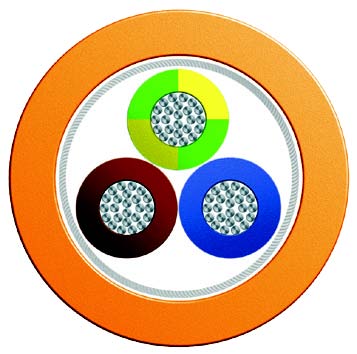
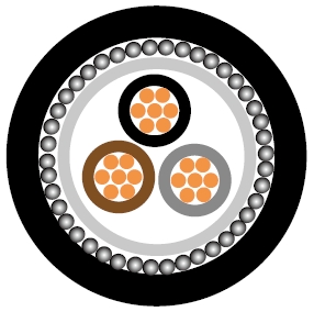
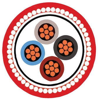
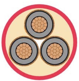
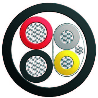
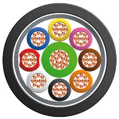
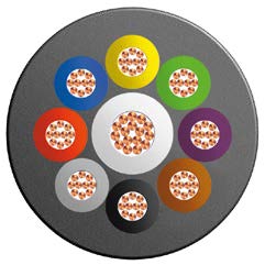
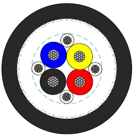
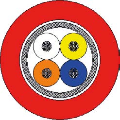
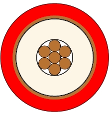
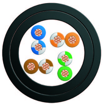
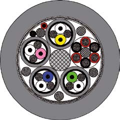
Cabling Element: Each two conductors are twisted together to form a pair.
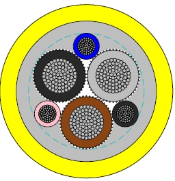
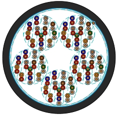
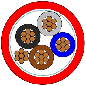
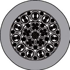
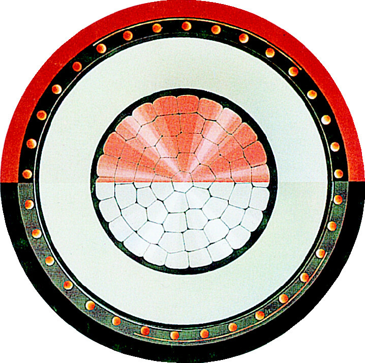
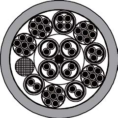
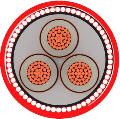
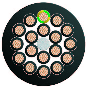
Stranding: For cables less than 15 pairs, pairs are helically stranded in concentric layers to form the cable core. For cables from 21 to 112 pairs, pairs are stranded in concentric layers or bundles to form the cables core.
Core Wrapping: One or more synthetic long ribbons or tapes are arranged on the cable core.
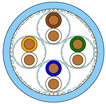
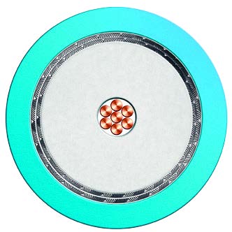
Screen: Aluminium/Polyester tape.
Drain Wire: A tinned copper drain wire, 0.5mm nominal diameter.
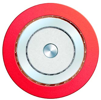
Sheath: Fire retardant LSZH.
Optional:Armoured Cables: For armoured cable, one or more tape(s) is (are) helically applied with overlap on the screen to form a bedding, and double steel tapes armour with a halogen-free fi re retardant outer sheath are applied on the bedding.
| Nominal Conductor Diameter | mm | 0.5 | 0.6 | 0.9 |
| Minimum Insulation Resistance | MΩ.km | 5000 | 5000 | 5000 |
| Maximum Operating Voltage | V | 200 | 200 | 400 |
| Maximum Permissible Current | A | 0.25 | 0.35 | 0.80 |
Minimum Bending Radius: 7.5×OD (unarmoured); 10×OD (armoured)
Temperature Range: -40℃ to +60℃ (during operation); -20℃ to +50℃ (during installation)
| Cable Code | Number of Pairs (n) | Nominal Sheath Thickness mm | Nominal Overall Diameter mm | Nominal Weight kg/km |
|---|---|---|---|---|
| 0.5mm Conductor, 0.9mm Insulated Wire | ||||
| BRAIL K24-2Y(L)H-2P0.5 | 2 | 1.0 | 6.0 | 55 |
| BRAIL K24-2Y(L)H-3P0.5 | 3 | 1.0 | 6.5 | 65 |
| BRAIL K24-2Y(L)H-5P0.5 | 5 | 1.0 | 7.0 | 80 |
| BRAIL K24-2Y(L)H-7P0.5 | 7 | 1.0 | 8.0 | 95 |
| BRAIL K24-2Y(L)H-10P0.5 | 10 | 1.0 | 9.0 | 120 |
| BRAIL K24-2Y(L)H-15P0.5 | 15 | 1.2 | 10.5 | 150 |
| BRAIL K24-2Y(L)H-21P0.5 | 21 | 1.2 | 12.5 | 185 |
| 0.6mm Conductor, 0.96mm Insulated Wire | ||||
| BRAIL K24-2Y(L)H-2P0.6 | 2 | 1.0 | 6.5 | 65 |
| BRAIL K24-2Y(L)H-3P0.6 | 3 | 1.0 | 7.0 | 70 |
| BRAIL K24-2Y(L)H-5P0.6 | 5 | 1.0 | 8.0 | 90 |
| BRAIL K24-2Y(L)H-7P0.6 | 7 | 1.0 | 8.5 | 110 |
| BRAIL K24-2Y(L)H-10P0.6 | 10 | 1.2 | 10.0 | 140 |
| BRAIL K24-2Y(L)H-15P0.6 | 15 | 1.2 | 11.5 | 175 |
| BRAIL K24-2Y(L)H-21P0.6 | 21 | 1.2 | 13.5 | 225 |
| 0.9mm Conductor, 1.5mm Insulated Wire | ||||
| BRAIL K24-2Y(L)H-2P0.9 | 2 | 1.0 | 8.5 | 95 |
| BRAIL K24-2Y(L)H-3P0.9 | 3 | 1.0 | 9.0 | 110 |
| BRAIL K24-2Y(L)H-5P0.9 | 5 | 1.0 | 10.5 | 150 |
| BRAIL K24-2Y(L)H-7P0.9 | 7 | 1.2 | 12.0 | 185 |
| BRAIL K24-2Y(L)H-10P0.9 | 10 | 1.2 | 13.5 | 245 |
| BRAIL K24-2Y(L)H-15P0.9 | 15 | 1.4 | 15.0 | 340 |
| BRAIL K24-2Y(L)H-21P0.9 | 21 | 1.4 | 19.0 | 435 |
| Cable Code | Number of Pairs (n) | Nominal Sheath Thickness mm | Nominal Overall Diameter mm | Nominal Weight kg/km | |
|---|---|---|---|---|---|
| Inner | Outer | ||||
| BRAIL K24-2Y(L)HBH-2P0.5 | 2 | 1.0 | 1.0 | 10.0 | 195 |
| BRAIL K24-2Y(L)HBH-3P0.5 | 3 | 1.0 | 1.0 | 10.5 | 205 |
| BRAIL K24-2Y(L)HBH-5P0.5 | 5 | 1.0 | 1.0 | 11.0 | 230 |
| BRAIL K24-2Y(L)HBH-7P0.5 | 7 | 1.0 | 1.0 | 12.0 | 255 |
| BRAIL K24-2Y(L)HBH-10P0.5 | 10 | 1.0 | 1.0 | 13.0 | 295 |
| BRAIL K24-2Y(L)HBH-15P0.5 | 15 | 1.0 | 1.2 | 14.5 | 345 |
| BRAIL K24-2Y(L)HBH-21P0.5 | 21 | 1.0 | 1.2 | 16.5 | 400 |
| 0.6mm Conductor, 0.96mm Insulated Wire | |||||
| BRAIL K24-2Y(L)HBH-2P0.6 | 2 | 1.0 | 1.0 | 10.5 | 200 |
| BRAIL K24-2Y(L)HBH-3P0.6 | 3 | 1.0 | 1.0 | 11.0 | 210 |
| BRAIL K24-2Y(L)HBH-5P0.6 | 5 | 1.0 | 1.0 | 12.0 | 245 |
| BRAIL K24-2Y(L)HBH-7P0.6 | 7 | 1.0 | 1.0 | 12.5 | 285 |
| BRAIL K24-2Y(L)HBH-10P0.6 | 10 | 1.0 | 1.2 | 14.0 | 330 |
| BRAIL K24-2Y(L)HBH-15P0.6 | 15 | 1.0 | 1.2 | 15.5 | 385 |
| BRAIL K24-2Y(L)HBH-21P0.6 | 21 | 1.0 | 1.2 | 18.0 | 450 |
| 0.9mm Conductor, 1.5mm Insulated Wire | |||||
| BRAIL K24-2Y(L)HBH-2P0.9 | 2 | 1.0 | 1.0 | 12.5 | 260 |
| BRAIL K24-2Y(L)HBH-3P0.9 | 3 | 1.0 | 1.0 | 13.5 | 285 |
| BRAIL K24-2Y(L)HBH-5P0.9 | 5 | 1.0 | 1.0 | 14.5 | 345 |
| BRAIL K24-2Y(L)HBH-7P0.9 | 7 | 1.0 | 1.2 | 16.0 | 395 |
| BRAIL K24-2Y(L)HBH-10P0.9 | 10 | 1.0 | 1.2 | 18.0 | 485 |
| BRAIL K24-2Y(L)HBH-15P0.9 | 15 | 1.0 | 1.4 | 19.5 | 610 |
| BRAIL K24-2Y(L)HBH-21P0.9 | 21 | 1.0 | 1.4 | 24.0 | 735 |