


The cables are designed for transmission of track circuit digicode signals up to 30 kHz in electrified lines.
EN 50266-2-4 & IEC 60332-3(Fire performance)
EN 50268-2(Smoke density)
EN 50267-2-1(Halogen content)
EN 50267-2-2(Gases acidity)
EN 50265-2-1, IEC 60332-1, NF C 32070 Cat C2 compliant (for PVC sheathed cables)
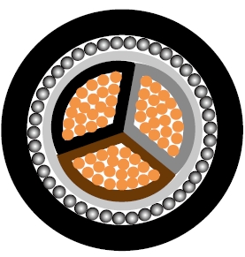
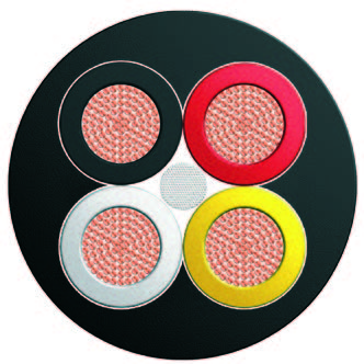
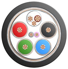
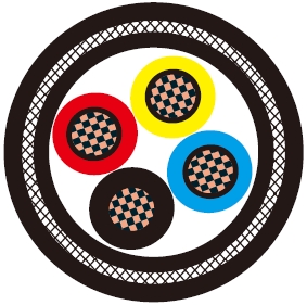
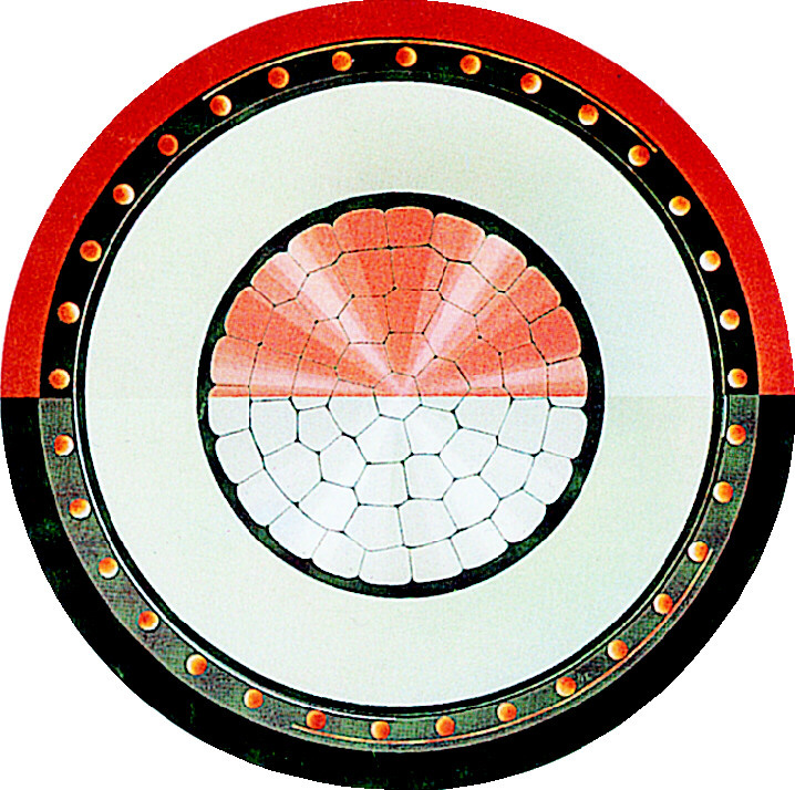
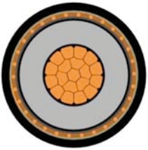
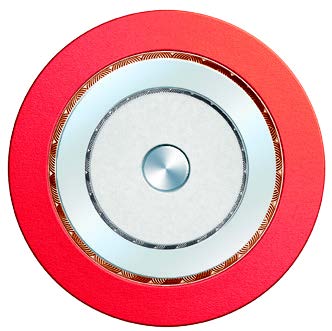
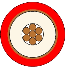
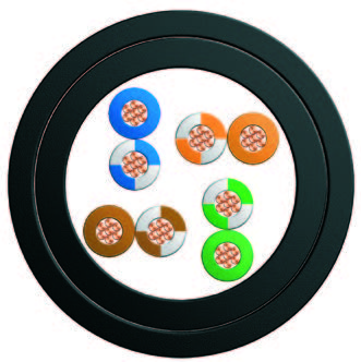
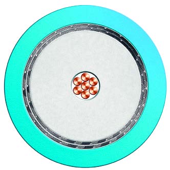
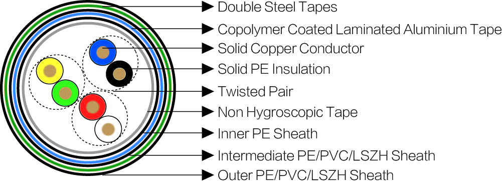
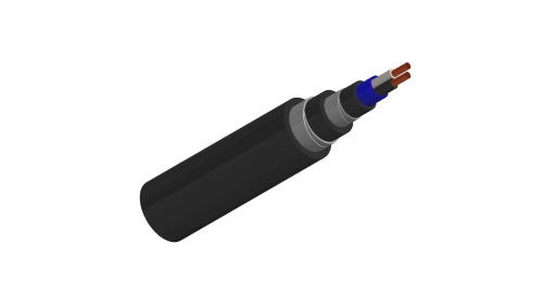
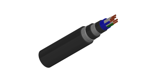
Electrical Characteristics at 20℃Conductors: Solid Annealed copper, 1.4 mm nominal diameter (0.6 mm for the auxiliary pair).
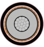
Insulation: Polyethylene.
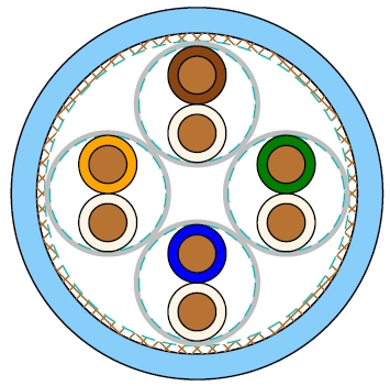
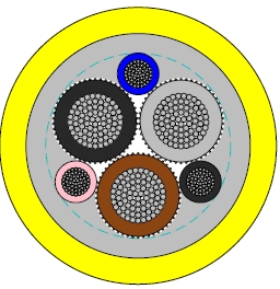
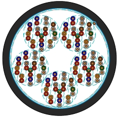
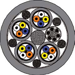
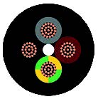
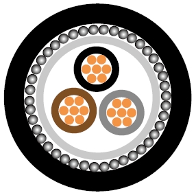
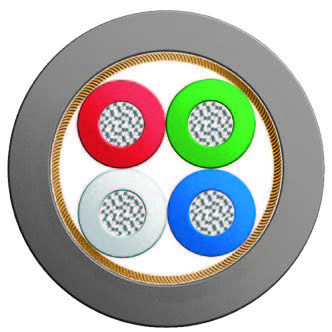
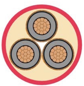
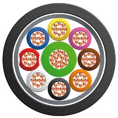
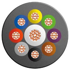
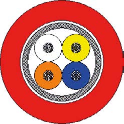
Cabling Element: Two insulated conductors are twisted together to form a pair.
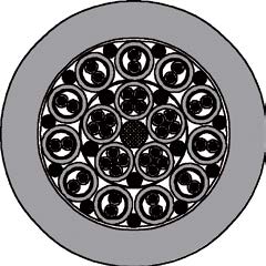
Stranding: Pairs are helically stranded to get the cable core.
Core Wrapping: Plastic tape(s) with overlapping.
Inner Sheath: Low density polyethylene.
Moisture Barrier: Copolymer coated laminated aluminium tape.
Intermediate Sheath: LSZH fi re retardant compound. PE or PVC option can be offered upon request.
Mechanical Protection: Two helically applied steel tapes.
Outer Sheath: LSZH fi re retardant compound. PE or PVC option can be offered upon request.
| Nominal Conductor Diameter | mm | 1.4 |
| Maximum DC Conductor Resistance | Ω/km | 12.1 |
| Maximum Resistance Unbalance | % | 3 |
| Minimum Insulation Resistance @500 V DC (1min) | MΩ.km | 5000 |
| Dielectric Strength (DC voltage 1 min) | ||
| Conductor to Conductor | V | 1000 |
| Conductor to Screen | V | 3000 |
| Minimum Spark Test On Outer Sheath (AC voltage) | V | 5000 |
| Maximum Mutual Capacitance (Data pairs) | nF/km | 45 |
| Nominal Mutual Capacitance (Auxiliary pair) | nF/km | 50 |
| Maximum Capacitance Unbalance | ||
| Pair to Pair | nF/500m | 400 |
| Pair to Ground | nF/500m | 1500 |
| Maximum Characteristic Pair Attenuation | ||
| @2.1KHz | dB/km | 0.64 |
| @4.1KHz | dB/km | 0.76 |
| @9.5KHz | dB/km | 1.05 |
| @20.7KHz | dB/km | 1.28 |
| Minimum Near End Crosstalk Attenuation (NEXT) | ||
| @4.1KHz | dB/km | 54 |
| @20.7KHz | dB/km | 42 |
| Minimum Far End Crosstalk Attenuation (FEXT) | ||
| @4.1KHz | dB/km | 59 |
| @20.7KHz | dB/km | 48 |
| Minimum Unbalance Attenuation | dB | 40 |
| Maximum Rated Voltage, between pair conductors | V rms | 220 |
| Maximum Rated Current | A rms | 1 |
Minimum Bending Radius: 8×OD (static); 16×OD (dynamic)
Temperature Range: -40℃ to +60℃ (during operation); -20℃ to +50℃ (during installation)
| Cable Code | Number of Pairs | Nominal Sheath Thickness mm | Nominal Overall Diameter mm | Nominal Weight kg/km | ||
|---|---|---|---|---|---|---|
| Inner | Interm. | Outer | ||||
| BRAIL DIG-2Y2Y(L)HBH-1P1.4 | 1* | 0.7 | 1.3 | 1.5 | 17.9 | 428 |
| BRAIL DIG-2Y2Y(L)HBH-2P1.4 | 2* | 0.7 | 1.3 | 1.5 | 19.2 | 497 |
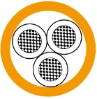
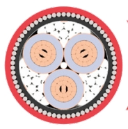
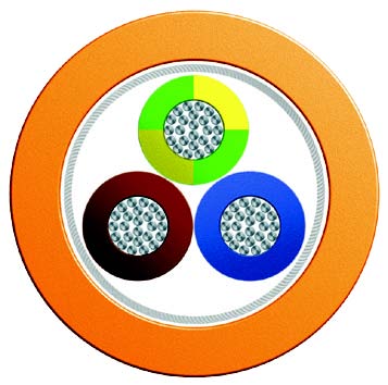
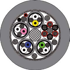
| BRAIL DIG-2Y2Y(L)HBH-3P1.4 | 3 | 0.7 | 1.3 | 1.5 | 20.2 | 562 |