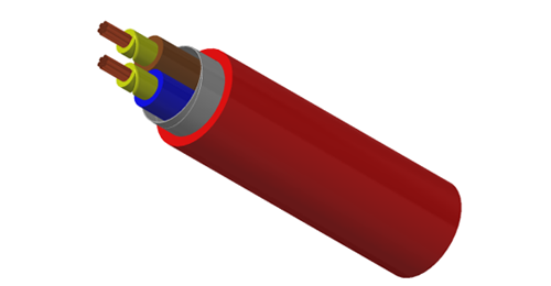
Successful EPC cable packages connect engineering decisions, purchasing documents and site execution. The approved cable schedule should travel with each purchase order, drum and installed circuit. This guide gives engineering, procurement and construction teams a practical framework for moving from an RFQ to a traceable handover.

Original AI-generated illustration: cable procurement and receiving coordination.
Freeze the design basis before comparing prices. Cross-section selection must address current capacity under the actual installation conditions, voltage drop, fault duty and protection coordination. Record the revision used for quotation and identify provisional quantities separately. See our LV cable sizing guide.
| RFQ item | Information to provide | Why it matters |
|---|---|---|
| Electrical duty | System voltage; load; fault level and clearing time; earthing arrangement. | Aligns insulation, conductor and screen requirements. |
| Cable construction | Conductor material/class; cores or pairs; size; insulation; screen; armour; sheath. | Creates a consistent basis for technical comparison. |
| Route and environment | Tray, duct or burial; grouping; ambient/soil conditions; water, UV and chemical exposure. | Connects cable selection to the real installation. |
| Fire performance | Required test, category and acceptance criteria for each performance objective. | Distinguishes flame spread, smoke, gases and circuit integrity. |
| Quantities and drums | Cable IDs; route lengths; termination allowances; continuous lengths; drum limits. | Supports cutting plans and avoids unintended joints. |
| Quality and delivery | Standards/editions; submittals; inspection points; destination; delivery sequence. | Makes approval and shipment milestones measurable. |
Specify both the cable product requirements and the installation rules adopted by the project. The following references have different scopes; agreement on one does not establish compliance with the others. Use the editions accepted by the contract and local authority.
| Reference | Scope relevant to an EPC package |
|---|---|
| IEC 60502-1:2021 | Construction, dimensions and tests for extruded-insulation power cables rated 1 kV and 3 kV. |
| IEC 60502-2:2014 + AMD1:2024 | Extruded-insulation power cables rated 6–30 kV; check the consolidated text including the July 2026 corrigendum. |
| IEC 60364-5-52:2009 + AMD1:2024 | Selection and erection of wiring systems in low-voltage installations. |
| IEC 60364-6:2016 | Initial and periodic verification of low-voltage electrical installations. |
Match instrumentation and data cables to the signal system as well as the route. For example, review individually screened instrumentation cable for the specified screening arrangement and RS485 databus cable for the network requirements. These are starting points for specification review, not interchangeable products.
Define fire requirements explicitly: IEC 60332 concerns flame propagation, while the applicable IEC 60331 part addresses circuit integrity under defined fire conditions. A low-smoke, halogen-free designation alone does not establish circuit integrity. State the required test part, conditions and duration for the intended circuit.
Use a technical compliance schedule with three clear entries for each requirement: offered value, supporting document and any proposed deviation. Resolve material substitutions and accessory interfaces before purchase-order release. Record approval responsibility and review dates in the inspection and test plan (ITP).
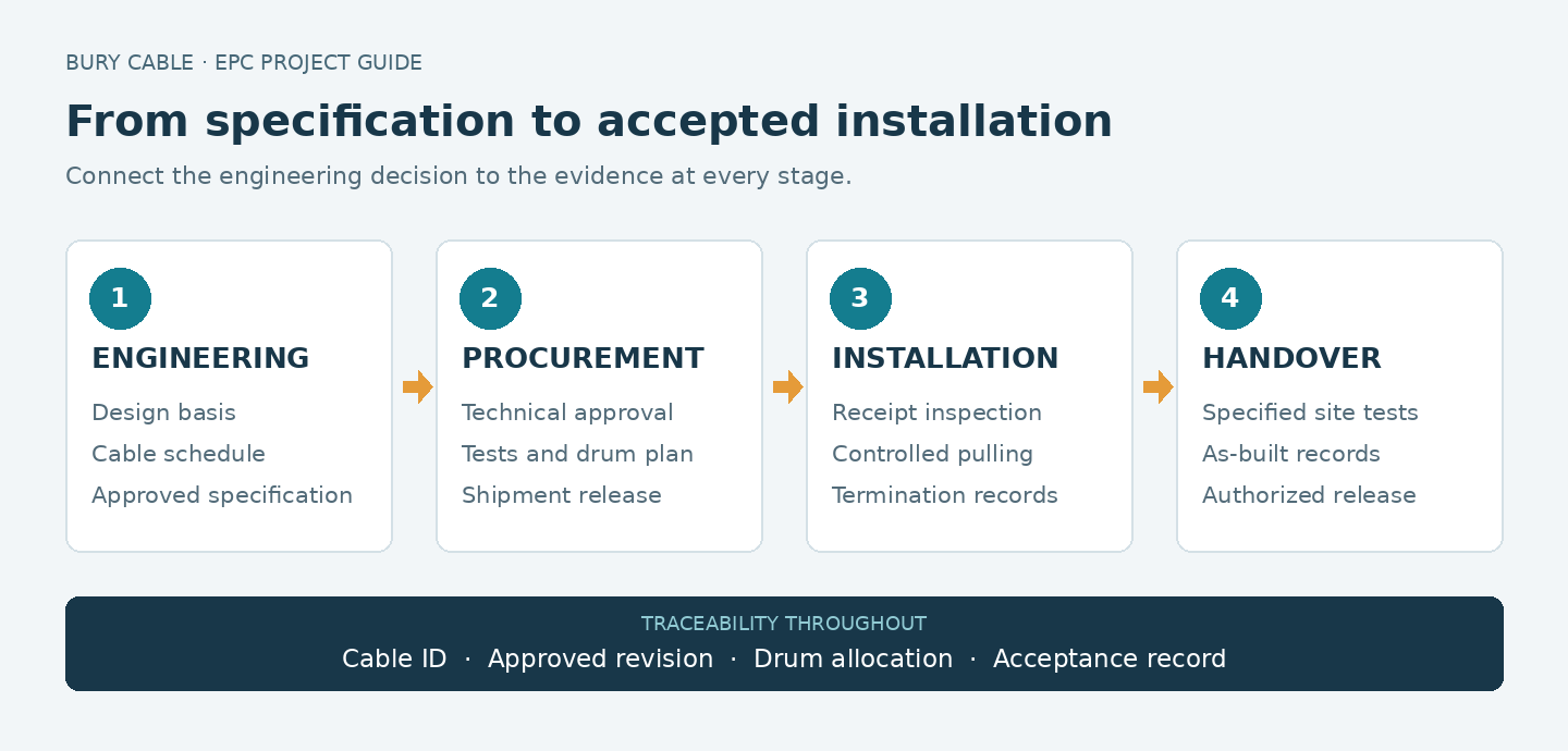
Keep cable IDs, approved revisions and inspection records connected through every stage.
Agree the datasheet revision, applicable routine/sample/type-test evidence and any factory acceptance testing (FAT) or witness points. Type-test reports, routine test records and a project FAT serve different purposes. Plan inspection notice periods and document review time into the delivery schedule.
Compare the evaluated package cost: cable, accessories, transport, drum handling, installation effort and documentation. Confirm commercial terms, delivery milestones and quotation validity. An attractive price per metre can lose its advantage if unsuitable drum lengths add joints or disrupt the installation sequence.
Illustrative cutting example: a measured route is 180 m. If the approved plan allows 4 m at each termination and a further 6 m for the defined routing allowance, the required continuous cut is 194 m. A 500 m drum can provide two such cuts, leaving 112 m before cutting losses. This is an example, not a standard allowance; allocate the remainder against another approved circuit before ordering.
| Receiving check | Record or action |
|---|---|
| Identity and length | Match purchase-order line, cable marking, drum number and declared length to the packing list. |
| Physical condition | Inspect drum flanges, battens, cable sheath and end seals; photograph and isolate damaged deliveries. |
| Supporting documents | Link the accepted datasheet and applicable test records to the delivered cable/drum identity. |
| Storage | Use suitable drained hardstanding, secure upright drums against rolling and protect cable ends and packaging. |
| Site allocation | Assign drums to routes and update remaining lengths after each cut; reseal exposed ends. |
Plan unloading with suitable lifting equipment and the supplier’s drum-handling instructions. Keep identification readable throughout storage. Check actual cable temperature against the approved handling limits before movement or installation, especially after cold storage.

Original AI-generated illustration: inspection of an installed cable route. Project drawings determine actual spacing and support arrangements.
Release a route-specific installation method statement before pulling. Confirm access, tray or duct readiness, bend locations, rollers, supports, pulling direction and communication arrangements. For long or complex pulls, assess tension and sidewall pressure against the approved cable and pulling-system limits.
Bends and pulling: use the manufacturer’s limits for the exact cable and pulling attachment. Distinguish installation bends from final-position bends and monitor pulling force.
Segregation and support: follow the approved power, control and instrumentation layout, EMC design and cable-cleat/support requirements.
Terminations: match glands, lugs and accessories to conductor material, dimensions, armour/screen construction and service conditions.
Bonding and earthing: implement the engineered screen, armour and protective-conductor arrangement; confirm interfaces before closing terminations.
Record field changes against cable IDs and update drawings before the next stage. A changed route, joint location or cable construction should pass the project’s design-change process. Use qualified personnel and the approved isolation, installation and test procedures.
Set acceptance criteria and responsibilities before testing. For LV installations, the adopted verification rules may include IEC 60364-6. MV cable tests require the applicable cable/accessory standards and approved project procedure. Select test methods, levels and durations for the actual system; factory test values are not universal site-test settings.
| Release point | Evidence to retain |
|---|---|
| Before manufacture | Approved construction, deviations, datasheet revision and agreed ITP. |
| Before shipment | Applicable test results, inspection release, packing list and drum schedule. |
| Before pulling | Accepted route, assigned drum, method statement and installation limits. |
| Before energization | Completed inspections and specified tests, resolved blocking defects and authorized release. |
| Final handover | As-built routes; cable/drum register; joint/termination records; test reports; operating documents. |
Each test record should identify the circuit, test method, conditions, instrument/calibration reference, result, acceptance criterion and responsible personnel. Carry outstanding items in a controlled punch list so the commissioning team can see exactly what has been accepted.
Send the cable schedule, construction and voltage requirements, installation conditions, applicable standards, required tests, drum lengths and delivery milestones. Attach the approved specification revision.
Agree them after route and termination allowances are defined, and before manufacture is released. Check site access, drum handling and the intended pulling sequence together.
Procurement secures the correct construction and documents early. Linking approved data, drum identities and inspection records to cable IDs gives commissioning teams a usable evidence trail.
Send BURY CABLE your cable schedule, project specification, destination and required delivery sequence for construction review and quotation. Include power, control, instrumentation and data requirements so the package can be reviewed consistently. Discuss your EPC cable requirements or explore our cable product range.
IEC scope references are linked in the standards table. Additional reading: IEC 60332-1-2:2025; IEC 60331-1:2018;