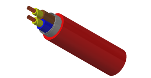
Control cables commonly connect command, switching and interlock circuits; instrumentation cables commonly carry measurement signals between field devices and control systems. Their applications overlap. A cable label alone cannot establish suitability for a PLC input, a transmitter loop or an actuator.
For EPC procurement, start with the circuit schedule and the connected equipment. Then specify conductor arrangement, electrical limits, screening and installation conditions. This guide explains the checks that matter when comparing control cable vs instrumentation cable.
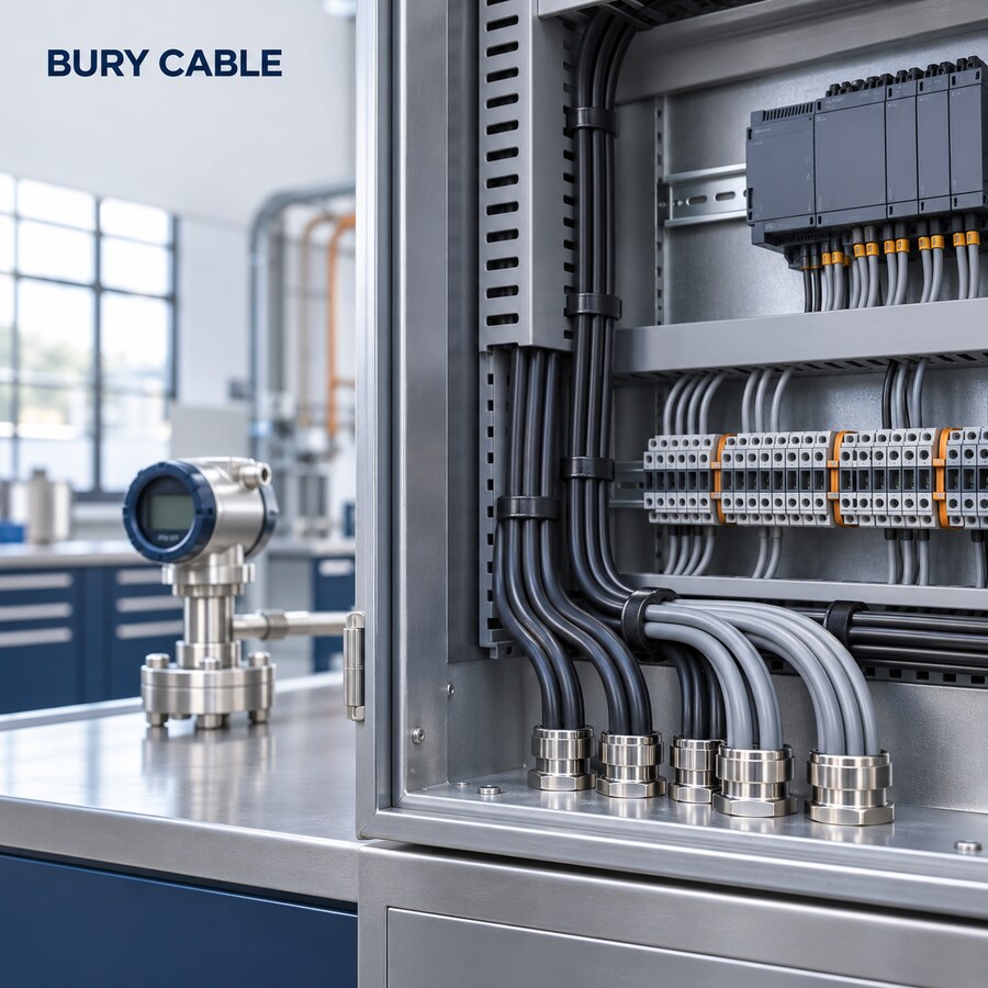
Illustration of control and measurement equipment. Cable selection starts with the circuit requirements.
Control cable is a broad description covering connections to switches, relays, sensors and actuators. Instrumentation designs often use pairs or triads to organise measurement channels. Screened and unscreened designs exist across industrial cable ranges. Neither name defines one universal voltage rating, conductor size or installation approval.
The following are common selection patterns. The approved data sheet and equipment instructions take precedence for the actual circuit.
| Selection point | Control circuits | Instrumentation circuits |
|---|---|---|
| Typical duty | Commands, status, interlocks and actuator control | Process measurements and associated control signals |
| Core arrangement | Often numbered or colour-coded multicore | Often pairs, triads or individually identified signal groups |
| Electrical check | Load current, voltage drop, insulation and protection | Loop resistance, capacitance and the receiving instrument limits |
| Screening | Unscreened or screened to suit the EMC design | Overall, individual or combined screens as specified |
| Shared checks | Route, environment, movement, fire requirements and terminals | The same installation checks still apply |
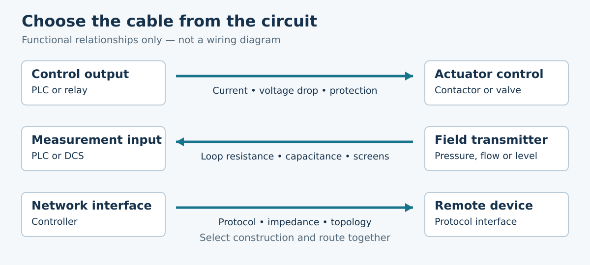
Classify circuits before choosing a cable family. The arrows show functional relationships, not terminal wiring.
A screened control cable can serve some measurement applications when its construction and electrical data meet the instrument requirements. Conversely, an instrumentation cable should not be substituted for an actuator circuit solely because it has spare cores.
Identify whether each connection is a dry contact, an electronic input, a relay coil or a powered actuator. Verify operating and starting current where applicable, acceptable voltage at the load and terminal capacity. Separate sensitive inputs from switching circuits according to the equipment and project EMC instructions. A flexible conductor does not establish suitability for repeated drag-chain motion.
For a two-wire 4–20 mA loop, include both cable conductors, the input burden and any barriers or isolators in the voltage budget. Use the instrument's minimum terminal voltage and maximum required loop current, including its alarm setting where applicable. Check conductor resistance at the design temperature. If HART is used, also check the specified network resistance and capacitance.
Illustrative resistance check: a 250 m one-way run with an assumed conductor resistance of 40 ohms/km has 20 ohms of cable loop resistance: 2 × 0.25 × 40. At 20 mA the cable drop is 0.4 V. These assumed values explain the method; they are not a BURY CABLE product rating or a complete loop approval.
For an RTD, match the two-, three- or four-wire connection and the receiving device's lead-resistance limits. Three-wire compensation depends on suitable resistance balance. For a thermocouple, specify the correct extension or compensating conductors, polarity and temperature range. Ordinary copper signal cable is not a general substitute. For RS-485, fieldbus or Ethernet, select a cable documented for the protocol and installation.
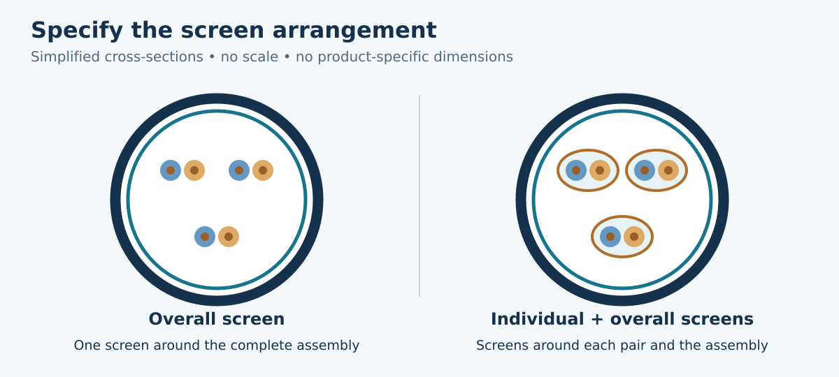
Screen arrangement is a separate specification from circuit type. Diagrams are schematic and do not represent a particular product.
Use these BURY CABLE ranges as starting points for a technical comparison. Confirm the exact size and approved construction before ordering; family names do not establish interchangeable ratings.
| Range | Construction to compare | Selection focus |
|---|---|---|
| YY LSZH | Unscreened multicore control cable | Control connections where the EMC design permits no screen |
| CY LSZH | Multicore cable with an overall copper braid | Screened control connections and compatible terminations |
| LIYCY | PVC signal and control cable with an overall screen | Core arrangement, conductor resistance and capacitance |
| LIYCY-TP | Twisted pairs with an overall screen | Paired signal routes; overall screening is not individual screening |
| LIYCY-CY | Individually and overall screened pairs | Channel separation and additional screen termination space |
| LIHCH / LIHCH-TP | Halogen-free screened signal constructions; TP uses pairs | Sheath and fire requirements alongside electrical suitability |
An overall screen surrounds the cable assembly; individual screens separate signal groups. Screen performance also depends on geometry, frequency and termination. Armour primarily addresses mechanical protection and is not equivalent to an individual signal screen.
Follow the instrument and project bonding instructions. Single-end and both-end screen connections have different uses; there is no universal rule for every circuit. A drain wire must not be assumed to be a protective earth conductor. See our guide to individual and overall cable screens.
Confirm bend radius, pulling limits, gland dimensions and separation from power cables before installation. An LSZH description does not establish circuit integrity during fire. Outdoor exposure, oil resistance and continuous movement also require explicit product evidence.
| RFQ item | Information to provide |
|---|---|
| Circuit and equipment | I/O schedule, signal type, device models, voltage and current |
| Cable construction | Core or pair count, spares, conductor area, screen arrangement and identification |
| Electrical limits | Resistance, capacitance and protocol requirements where relevant |
| Installation | Route length, fixed or moving duty, temperature, UV, moisture, chemicals and mechanical protection |
| Acceptance and delivery | Required standards, test records, drum lengths, marking and traceability |
Review substitutions against the same schedule, including terminals and glands. Record deviations before purchase. Use the EPC cable procurement checklist to coordinate approval, delivery and site records.
Only after the circuit requirements have been checked. Compare core grouping, screen arrangement, resistance, capacitance, voltage rating and installation conditions. Matching conductor size alone is insufficient.
No. Overall screening may be suitable for compatible circuits. Individual screens may be required for channel separation or by the equipment specification. Select the arrangement from the interference assessment and instrument instructions.
No. Pairing alone does not establish the required impedance, attenuation, capacitance or installation performance. Use a cable whose documented data meet the network requirements.
Check identification, continuity, polarity, screen connections and the approved loop drawings. Follow the equipment procedure for insulation tests and isolate sensitive electronics as required. Record results against cable and instrument tags.
Preparing a cable enquiry? Send the circuit schedule, route conditions and required construction to BURY CABLE so the proposed cable can be checked against your project requirements.
Technical background: HELU control cables; Belden signal application example; Beckhoff RTD connection techniques; WIKA thermocouple guidance.