







Earth fault current Duration Earthing arrangement IEC 60502 2 and IEC 60949
Executive summary
The metallic screen of a medium voltage cable controls the electric field around the insulation, provides a defined path for charging and earth fault currents, and supports safe operation of the cable system. Its required cross sectional area is therefore a system design result, not a cosmetic construction detail.
For an IEC 60502-2 cable, the purchaser should provide the prospective earth fault current, protection clearing time, screen bonding arrangement and required screen material. The designer or manufacturer can then verify the thermally permissible short circuit current using the applicable method, commonly IEC 60949, and confirm that accessories and earth connections have matching duty.
Input | Why it matters | Typical RFQ wording |
Earth fault current | Defines the current the screen system may have to carry. | 25 kA earth fault current |
Clearing time | Heating increases with fault duration. | 25 kA for 1 second |
Bonding method | Determines current sharing and normal induced currents. | Both ends bonded or single point bonded |
Screen material | Copper wire, tape or metallic sheath have different behaviour. | Copper wire screen |
Installation layout | Single core cable spacing and formation affect induced voltage and losses. | Trefoil in buried ducts |
1 What the metallic screen does
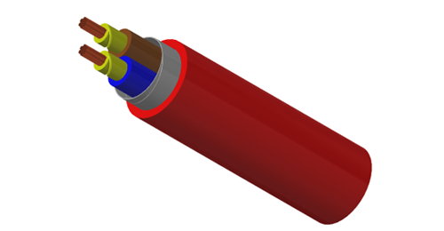
A medium voltage cable normally includes a conductor screen, extruded insulation, an insulation screen and a metallic screen. The semiconductive layers shape the electric field; the metallic screen is the conductive layer outside them. Depending on the system design, it may be formed from copper wires, copper tape, a concentric conductor or a metallic sheath.
Maintains the outer surface of the insulation screen near earth potential.
Carries capacitive charging current during normal service.
Provides a path for earth fault current and enables protective devices to operate.
Limits touch voltage when the screen and accessory earthing system are correctly designed.
May contribute to radial moisture protection when a continuous metallic sheath or laminate is used, but a wire screen alone is not automatically a radial water barrier.
2 Which standards are relevant
IEC 60502-2 specifies construction, dimensions and test requirements for extruded insulated power cables from 6 kV up to 30 kV for fixed installations. Its current consolidated edition is IEC 60502-2:2014+AMD1:2024. It establishes the cable framework, but a project still has to state the fault duty and bonding conditions needed to select the metallic screen.
IEC 60502-2:2014+AMD1:2024 official publication page
IEC 60949 provides a method for calculating thermally permissible short circuit currents, including a non adiabatic correction where applicable. IEC 60909-3 addresses current distribution and reduction factors for cable screens or sheaths in certain earthed systems. The project engineer should also apply the local wiring rules, utility requirements and accessory manufacturer instructions.
IEC 60949 official publication page | IEC 60909-3 official publication page
3 The basic thermal sizing relationship
For a preliminary adiabatic check, the familiar relationship can be written as:
S = I √t / k
Symbol | Meaning |
S | Required effective metallic screen area in mm² |
I | RMS fault current carried by the screen in A |
t | Fault duration in seconds |
k | Material and temperature factor based on the applicable calculation method |
The equation shows why “16 mm² copper screen” is not a complete design statement. Doubling the current doubles the area required under the same assumptions, while increasing the clearing time from 0.25 second to 1 second doubles the area because the relationship follows the square root of time.
Important: the current inserted in the calculation is the portion actually carried by the cable screen, not automatically the full three phase short circuit current. Current division through screens, earth conductors, armour, parallel cables and the general earthing system must be established by the system designer. The value of k must not be guessed; it depends on the conductor material, initial temperature, final permissible temperature and the selected standard method.
4 The five decisions that control screen size
Earth fault current and protective clearing time
Use the maximum prospective earth fault current at the relevant location and the total time needed for protection and the switching device to clear the fault. If primary and backup protection have different times, the project may require verification against both duties.
Screen bonding arrangement
Both ends bonding gives a continuous return path but can create circulating currents in single core systems, increasing losses and reducing ampacity. Single point bonding suppresses circulating current in normal service but creates a standing induced voltage at the open end and normally requires a sheath voltage limiter. Cross bonding is used on longer routes to reduce induced voltage and circulating losses, but it requires sectionalised screens, correctly transposed minor sections and carefully coordinated link boxes.
Bonding arrangement | Normal service effect | Fault design point |
Both ends bonded | Possible circulating screen current and additional losses. | Check current division through both screen earth connections. |
Single point bonded | No closed loop circulating current; induced voltage appears at the open end. | Check screen voltage, SVL duty and fault path. |
Cross bonded | Induced voltages largely cancel across complete major sections. | Check every section, joint, link box and bonding lead. |
Special bonding | Project specific behaviour. | Use a complete cable system study, not a catalogue assumption. |
Metallic construction and effective area
Copper wire screens provide distributed conductive area and are common in IEC medium voltage designs. Copper tape may control the field and provide a defined conductive layer, but thin tape should not be assumed to have the same earth fault capability as a specified wire screen. Aluminium laminate or lead sheath may serve moisture or chemical protection functions; their contribution to fault current depends on continuity, joints, terminations and the approved system design.
Parallel paths and accessories
The cable screen is only one part of the earth fault loop. Armour, a separate earth conductor, nearby metallic structures and parallel circuits may share current. Conversely, an undersized bonding lead, link box connection or termination earth braid can become the weakest point even when the cable screen itself passes the thermal calculation.
Installation and operating temperature
The screen temperature before the fault is influenced by cable loading, ambient conditions and screen losses. Single core formation, spacing, soil thermal resistivity, duct arrangement and bonding all affect operating temperature and ampacity. Screen sizing and ampacity studies should therefore use consistent installation assumptions.
5 Why catalogue screen sizes cannot be copied blindly
Many data sheets offer standard copper screen sizes such as 16, 25, 35 or 50 mm². These are manufacturing options, not universal ratings. Two projects using the same 12/20 kV 1 x 240 mm² cable may require different screens because one network clears an earth fault in 0.2 second while another requires 1 second, or because their bonding and parallel earth paths differ.
Incorrect shortcut | Why it fails | Better requirement |
Match screen to phase conductor size | Fault duty does not scale directly with load current. | State earth fault current and duration. |
Use the manufacturer standard screen | A standard option may not match the project duty. | Request a documented thermal verification. |
Treat armour as guaranteed parallel earth | Current sharing depends on material, continuity and terminations. | Define whether armour contribution is permitted. |
Check cable but not accessories | Bonding leads and connectors may have lower capacity. | Verify the complete cable system. |
Specify only 25 kA | Duration changes the thermal requirement materially. | Write 25 kA for 1 s or the actual duty. |
6 Information to include in an MV cable enquiry
Rated voltage U0/U (Um), system voltage and frequency.
Single core or three core construction, conductor material and conductor size.
Maximum earth fault current at the cable location and required duration.
Screen material and any minimum screen area required by the utility or consultant.
Screen bonding method, link box arrangement and whether sheath voltage limiters are used.
Installation method, route length, cable formation, spacing and number of parallel circuits.
Separate earth conductor, armour continuity and permitted parallel return paths.
Insulation and outer sheath materials, water blocking and radial moisture barrier requirements.
Applicable standard and edition, routine tests, type tests and project specific tests.
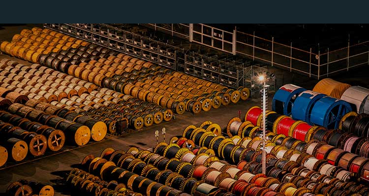
Required drum lengths, quantity, destination and accessory scope.
7 Example procurement workflow
Step | Action | Output |
1 | Complete the network fault study. | Maximum screen current and clearing time. |
2 | Choose the bonding concept for the route. | Both ends, single point or cross bonded design. |
3 | Calculate screen thermal duty and induced voltage. | Minimum effective area and SVL requirement. |
4 | Select cable construction and accessories. | Coordinated cable, joints, terminations and link boxes. |
5 | Check ampacity with screen losses included. | Validated continuous current rating. |
6 | Review supplier evidence. | Calculation sheet, datasheet and test documentation. |
7 | Verify installation and commissioning records. | As built bonding continuity and test results. |
8 Documents buyers should request
For a project specific MV cable, the technical submittal should identify the metallic screen material and nominal cross sectional area, screen short circuit rating and duration, bonding assumptions, conductor and insulation temperatures used, and the calculation method. It should also include a construction drawing, cable datasheet, applicable type test evidence, routine test schedule, drum schedule and accessory data where these items are within supply scope.
If the quotation states a screen size without the fault current or duration used to select it, ask for clarification before technical approval. A compliant cable design and an adequately rated installed cable system are related, but they are not the same decision.
9 Common questions
Is a larger copper screen always better
Not automatically. A larger screen can increase fault capacity, but it also adds copper, weight, diameter and cost. In both ends bonded single core systems it can influence circulating losses. Select the size that satisfies the documented system duty with the required margin.
Does IEC 60502 2 prescribe one screen size for each conductor size
No universal project screen size can be inferred from the phase conductor alone. IEC 60502-2 defines the cable construction and test framework; the purchaser must still communicate the system and fault requirements needed for application design.
Can steel wire armour replace the copper screen
Armour and screen perform different primary functions. Any armour contribution to earth fault current must be established through a system calculation and reliable electrical continuity at joints and terminations. It should not be assumed silently.
Is the screen rating the same as the conductor short circuit rating
No. The phase conductor and metallic screen have different areas, temperatures, materials and current duties. Each must be checked for the applicable fault condition.
Conclusion
The correct metallic screen size for a medium voltage cable begins with the network, not the catalogue. Earth fault current, clearing time, bonding arrangement, temperature assumptions, current sharing and accessory ratings must be considered together. IEC 60502-2 provides the cable construction and testing framework, while methods such as IEC 60949 support the thermal short circuit calculation.
For an accurate BURY CABLE quotation, provide the rated voltage, conductor size, number of cores, earth fault current and duration, bonding arrangement, installation method, quantity and required drum lengths.
[email protected] | www.burycable.com
Related reading and official references
Understanding IEC 60502-1 Power Cables
Lead Covered Armoured Cables for Oil Gas and Petrochemical Projects
IEC 60949 Calculation of Thermally Permissible Short Circuit Currents
IEC 60909-3 Short Circuit Currents in Three Phase AC Systems


