





VFD Cable Selection Guide
EMC Shielding, Symmetrical Grounding and Installation
Executive Summary




VFD Cable Selection Guide
EMC Shielding, Symmetrical Grounding and Installation
Executive Summary
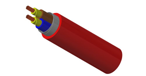
Variable-frequency drives (VFDs), also called variable-speed drives (VSDs), control motor speed by converting incoming power into a pulse-width-modulated output. The cable between the drive and motor therefore operates in a switching environment that is different from a conventional sinusoidal supply. A cable may have adequate ampacity and still be a weak choice for a VFD circuit if its insulation, grounding symmetry, screen conductivity or termination method does not match the drive system. The practical risks include electromagnetic interference (EMI), nuisance effects on nearby instrumentation, common-mode current, additional stress on motor insulation, bearing-current pathways and non-compliant installation details. This guide explains how engineers, EPC contractors and purchasing teams can specify VFD motor cable more accurately. BURY CABLE's related product range includes copper-tape screened VSD/EMC cable for fixed installations and flexible VSD/EMC cable for applications where increased flexibility is required. Key Selection Decisions Decision What must be confirmed Why it matters Electrical duty System voltage, motor full-load current, overload duty, switching frequency and cable length Determines conductor size, thermal duty, insulation stress and drive-output accessories. EMC control Screen material, coverage, conductivity and 360° termination method Controls the high-frequency return path and radiated emissions. Grounding Protective earth size, symmetrical arrangement and bonding at both ends Supports safety and reduces imbalance in common-mode current paths. Mechanical duty Fixed, occasional movement, continuous flexing, torsion, tray, conduit or burial Determines conductor class, sheath and minimum bending performance. Environment Temperature, oil, UV, water, chemicals, flame performance and LSZH requirement Prevents premature material degradation and specification mismatch. Documentation Cable standard, drive-manufacturer instructions, datasheet, tests and project approvals Keeps the quotation, submittal and installation on the same technical basis. 1. What Is a VFD Cable? A VFD cable is a power cable designed for the connection between a variable-frequency drive and an AC motor. Its core duty is still power transmission, but the construction is optimized for a PWM drive output and the electromagnetic environment created by fast switching. Typical VFD cable architecture uses three insulated phase conductors, one or more protective-earth conductors, an overall metallic screen and an outer sheath selected for the installation environment. Many industrial designs place three earth conductors symmetrically around the phase conductors. This balanced geometry is widely preferred for EMC performance, although the exact protective-earth area must still comply with the applicable standard and local rules. IMPORTANT DISTINCTION A VFD cable is not a communication cable. It carries motor power. Control, encoder, feedback and fieldbus circuits normally require their own cable types and routing rules. VFD Cable vs Conventional Power and Control Cable Cable type Primary purpose Typical construction direction Selection warning VFD / VSD motor cable Drive-to-motor power Three phases, symmetrical PE, conductive EMC screen, suitable insulation and sheath Confirm termination method and drive-specific length limits. Conventional power cable Sinusoidal mains or distribution Phase conductors plus PE; screen may not be designed for high-frequency return current Ampacity alone does not demonstrate EMC suitability for a PWM output. Control cable Control circuits and discrete signals Multicore construction; screened or unscreened depending on signal Not suitable as a substitute for motor power cable. Instrumentation / data cable Low-level analog or digital signals Twisted pairs, individual/overall screens, controlled capacitance or impedance Route separately from VFD motor cables according to system instructions. 2. Why PWM Motor Outputs Change Cable Requirements A VFD does not simply reduce the mains voltage. It switches semiconductor devices rapidly to create a pulse-width-modulated waveform whose average value controls motor speed and torque. The resulting cable current contains the intended motor current plus higher-frequency components and common-mode current paths. At these frequencies, cable geometry and screen termination become more important. A long, narrow screen pigtail can have significant high-frequency impedance even when its DC resistance appears low. A properly bonded screen provides a lower-impedance return path and helps contain radiated noise. Cable length, motor insulation, drive output characteristics and any output reactor or filter also interact; there is no single universal maximum motor-cable length. The system designer should review the drive manual rather than applying a generic distance rule. Rockwell Automation's PWM drive guidance, for example, provides product-specific motor-cable length tables and separate recommendations for grounding, routing and output devices. ABB drive guidance recommends symmetrical shielded VFD cable for EMC performance and notes related benefits for bearing current, wear and motor-insulation stress. Engineering references: ABB ACS580 quick installation guide Engineering references: Rockwell Automation PWM drive wiring and grounding manual 3. Recommended VFD Cable Construction The approved construction must follow the destination-market standard, project specification and drive manufacturer's instructions. The components below describe a common industrial design direction rather than one universal cable recipe. Component Common selection Engineering purpose Confirm before order Phase conductors Copper, class 2 for fixed or class 5 for flexible designs Carries motor current and overload duty Cross-section, conductor class, resistance and temperature rating. Insulation XLPE or another thermoset; selected flexible designs may use PVC or TPE systems Withstands operating temperature and switching-related electrical stress Voltage rating, material designation, thickness and compatibility with the drive. Protective earth One full-size PE or three symmetrical PE conductors, depending on design Protective bonding and common-mode return path Total PE area, arrangement, identification and local-code compliance. Metallic screen Copper tape, braid, foil/braid or another approved conductive screen Contains emissions and carries high-frequency return current Coverage, conductivity, overlap, transfer impedance where specified and termination hardware. Outer sheath PVC, LSZH, PE, TPE, PUR or project-specific compound Mechanical and environmental protection UV, oil, chemical, flame, smoke, temperature and movement requirements. 4. EMC Screen Options: Copper Tape, Braid or Foil/Braid The most visible difference between VFD cable designs is often the screen. Screen selection should consider conductivity, coverage, flexibility, installation method, termination hardware and the frequency range of concern. A percentage-coverage claim alone is not a complete EMC specification. Screen type Typical strength Typical limitation Best fit Copper tape High circumferential coverage and robust fixed-installation screen Less flexible than braid; termination must preserve circumferential contact Fixed industrial runs, tray, conduit and installations using compatible EMC glands or kits. Copper braid Good flexibility and mechanically durable termination surface Coverage and high-frequency performance depend on braid design and copper content Flexible VFD cables and machinery where bending is expected. Foil + braid Foil supports near-continuous coverage while braid improves conductivity and termination Construction quality and termination are critical; a drain wire alone should not replace proper 360° bonding Compact or flexible designs requiring broad-band screening. Armour only Provides mechanical protection and may participate in bonding when designed for it Armour is not automatically an EMC screen and may not provide the required high-frequency path Use only when the complete cable and termination design explicitly address both mechanical and EMC duties. PROCUREMENT NOTE Ask for the screen material, nominal coverage or overlap, conductor/earth arrangement and recommended termination method. The words 'screened cable' are not sufficient for a technically comparable quotation. 5. Symmetrical Grounding and Shield Bonding A symmetrical cable geometry reduces imbalance among the three phases and provides evenly distributed protective-earth paths. This is one reason many drive manufacturers prefer a symmetrical shielded motor cable. The arrangement is particularly relevant where high-frequency common-mode current can otherwise seek unintended return paths through bearings, structures, trays or adjacent wiring. For EMC control, drive manufacturers commonly require the motor-cable screen to be bonded at both the drive and motor ends with low-impedance, circumferential contact. Rockwell Automation specifically describes bonding at both ends so the screen can provide a return path for stray high-frequency current. The exact terminal, gland, connector or clamp must match the drive, motor terminal box and cable design. This does not replace protective-earthing requirements. The screen, protective-earth conductor and equipotential bonding system have related but distinct functions. The installation must follow the drive manual, motor documentation, local electrical code and project grounding philosophy. 6. Insulation, Voltage Rating and Thermal Duty The cable voltage designation must match the system and the approved drive-to-motor design, but nominal system voltage is not the only consideration. PWM switching can produce reflected-wave effects and additional electrical stress, especially with longer cables and fast rise times. The drive and motor manufacturers may therefore specify cable-length limits, motor-insulation requirements or output reactors, filters and terminators. XLPE and other thermoset insulation systems are widely used in industrial VFD cables because of their thermal and dielectric properties. Flexible designs may use alternative insulation and sheath systems to meet bending requirements. The buyer should not infer performance only from the generic material name: compound grade, wall thickness, conductor temperature and test standard all matter. Confirm the drive output voltage, motor rated voltage, motor full-load current and overload profile. Confirm the cable voltage rating required by the drive manufacturer and destination-market rules. Check ambient temperature, grouping, tray/conduit/burial conditions and thermal derating. Check motor-cable length against the exact drive model, carrier-frequency setting and any output filter or reactor. Confirm whether the motor insulation system is suitable for inverter duty and the proposed cable length. 7. Fixed vs Flexible VFD Cable Flexible conductor does not automatically mean continuous-flex cable. A class 5 conductor improves handling, but repeated bending, drag-chain movement, festoon travel, torsion and reeling each require a purpose-designed construction and declared mechanical limits. Installation duty Recommended direction Key checks Fixed tray, conduit or duct Class 2 conductor with copper-tape or other approved EMC screen Bending radius, pulling tension, screen termination, fire/environment rating. Occasional movement during installation or maintenance Class 5 flexible VFD cable Minimum bend radius, conductor flexibility, gland compatibility and fatigue expectation. Continuous flex in drag chain Purpose-designed continuous-flex VFD cable Cycles, speed, acceleration, travel, bend radius, torsion and oil/coolant exposure. Torsion, reeling or festoon Application-specific dynamic cable Do not substitute a generic flexible VFD cable; confirm torsion angle, tensile load and operating cycles. Outdoor or wet area UV/moisture-resistant sheath and suitable ingress-protected terminations Water exposure, sunlight, temperature, burial/duct conditions and metallic-part corrosion. For related options, review BURY CABLE's fixed copper-tape screened VSD/EMC cable and flexible VSD/EMC cable. Final suitability depends on the approved project specification. 8. Cable Sizing and Motor-Cable Length VFD cable conductor size is normally selected from the motor current and installation conditions, not only from motor power in kilowatts. The current rating must cover continuous load, overload duty, ambient temperature, grouping, installation method and any harmonics or manufacturer-specific derating. Voltage drop and starting behavior should be checked where relevant, although a VFD start is not equivalent to direct-on-line starting. Motor-cable length can affect reflected voltage, leakage/common-mode current, EMC emissions and drive protection. The allowable length may change with drive frame, output voltage, switching frequency, cable type, motor insulation and use of a reactor, dV/dt filter, sine-wave filter or terminator. Use the exact drive manual and do not publish a universal maximum distance in the purchase order. A BETTER RFQ Instead of writing 'VFD cable, 4C x 35 mm²', state the drive model/output voltage, motor current, approximate route length, fixed or flexible duty, screen and PE arrangement, installation method, environment, standard and required documentation. 9. Installation and Termination Best Practices Good cable cannot compensate for poor routing or termination. The following sequence is a practical review checklist; it does not replace the drive manufacturer's instructions. Confirm the complete drive-to-motor system. Record the drive model, motor data, cable length, switching-frequency setting and any output reactor or filter. Use the specified motor cable. Verify conductor size, voltage rating, symmetrical PE arrangement, screen design, sheath and movement duty against the approved datasheet. Maintain 360° shield contact. Use a compatible EMC gland, clamp, connector or termination kit. Avoid long screen pigtails unless the equipment manufacturer specifically permits them. Bond at both ends as instructed. Connect the screen at the VFD cabinet and motor frame/terminal box using the manufacturer's grounding arrangement. Preserve protective earthing. Do not treat the cable screen as an undocumented substitute for the required protective-earth conductor. Separate power and sensitive signals. Follow the drive manufacturer's routing distances and crossing rules for control, encoder, instrumentation and communication cables. Control parallel runs and crossings. Where circuits must cross, use the routing geometry specified by the equipment manufacturer and keep parallel exposure as short as practical. Respect mechanical limits. Observe pulling tension, minimum bending radius, support spacing, gland entry and dynamic-flex limits. Inspect the finished installation. Verify screen continuity, bond quality, PE connection, gland contact, phase identification, insulation test method and torque values before energization. 10. Standards: What They Do - and Do Not - Prove IEC 61800-3:2022 is the current IEC product EMC standard for adjustable-speed power drive systems and machine tools. It specifies EMC requirements and test methods for the drive system. It should not be presented as a cable construction certificate. A cable can support an IEC 61800-3 compliant installation, but system compliance depends on the drive, filters, cable, motor, enclosure, grounding, routing and installation together. IEC 61800-5-1:2022 addresses safety requirements for adjustable-speed power drive systems with respect to electrical, thermal, fire, mechanical, energy and other hazards. Again, it is a drive-system standard, not a substitute for the cable's own construction and test standard. The cable itself may be manufactured to a national or international power-cable standard, a manufacturer specification or a project-specific design. For example, BURY CABLE's Australian-market VSD/EMC product pages reference AS/NZS 5000.1 together with relevant material and conductor standards. The applicable standard must be confirmed for the destination country and project. Reference Scope in a VFD project Procurement use IEC 61800-3:2022 EMC requirements and specific test methods for PDS and machine tools Use for system EMC design/assessment; do not claim it as the cable construction standard. IEC 61800-5-1:2022 Safety requirements for adjustable-speed PDS Use for drive-system safety context and equipment compliance. Cable construction standard Conductor, insulation, sheath, dimensions and cable tests State the exact standard/edition or approved manufacturer specification on RFQ and PO. Drive manufacturer manual Cable type, routing, grounding, length limits and output accessories Use the exact drive model and revision as an installation design input. Project/local rules Earthing, fire, installation method, approvals and inspection Apply the destination-country and project requirements in addition to product data. Official standard page: IEC 61800-3:2022 Official standard page: IEC 61800-5-1:2022 11. Application Selection Matrix Application Cable direction Additional checks Pumps, fans and compressors Fixed shielded VFD cable; copper-tape or braid screen according to route Motor-cable length, moisture, UV, temperature, tray/conduit and termination space. Machine tools and factory automation Flexible or fixed VFD cable depending on machine movement Oil/coolant, continuous flex, encoder separation, compact gland entry and EMC bonding. Water and wastewater plants Screened cable with moisture/chemical-resistant sheath; armour if mechanical risk requires it Wet areas, corrosive atmosphere, direct burial/duct, motor terminal-box ingress protection. Mining and heavy industry Mechanically robust VFD cable designed for the voltage and movement duty Abrasion, impact, trailing/reeling, local mining standard and inspection regime. HVAC in buildings/data centres LSZH or project-specified fire-performance VFD cable where required Fire strategy, cable route, EMC near controls/BMS, CPR or local building requirements. Marine and offshore Approved marine/offshore VFD cable with compatible screen and sheath Class/flag requirements, oil/mud resistance, flame/smoke tests, corrosion and EMC zoning. Explore additional cable categories for automation and process control or review the full BURY CABLE product range. 12. Information Required for an Accurate Quotation Drive manufacturer, model, output voltage and rated output current. Motor power, rated voltage, full-load current, insulation class and inverter-duty status. Cable route length, installation method and approximate vertical/horizontal routing. Conductor size or design current, number and arrangement of phase/PE conductors. Fixed, flexible, continuous-flex, torsion, reeling or trailing duty. Screen type, coverage/conductivity requirement and proposed termination method. Sheath material and oil, UV, water, chemical, temperature and fire-performance requirements. Applicable cable standard, project specification, destination country and approvals. Quantity, drum lengths, delivery destination, inspection and document requirements. Send the cable schedule, drive datasheet and route information through the BURY CABLE contact page for a technical review before quotation. 13. Common Specification Mistakes Selecting by conductor size alone A description such as '4C x 35 mm² screened cable' does not define the PE arrangement, screen material, insulation system, movement duty or termination method. Treating armour as an automatic EMC screen Armour can provide valuable mechanical protection, but it should not be assumed to deliver the required high-frequency screen performance unless the complete cable and termination design demonstrate that function. Using flexible cable for continuous flex without verification Conductor flexibility alone does not establish drag-chain, torsion, reeling or festoon capability. The dynamic application must be declared. Ignoring termination hardware The screen may be technically suitable but ineffective if the gland or clamp cannot maintain low-impedance circumferential contact at the drive and motor. Claiming IEC 61800-3 cable certification IEC 61800-3 is an EMC standard for the drive system. The cable needs its own construction/testing basis, and the installed system must be assessed as a whole. 14. Frequently Asked Questions Can ordinary power cable be used between a VFD and motor? Only when the drive manufacturer, project design and local rules allow it for the specific voltage, current, cable length and EMC environment. A conventional cable may carry the current but lack the preferred symmetrical PE arrangement, screen conductivity or termination system. Should the VFD cable screen be grounded at one end or both ends? Drive manufacturers commonly require low-impedance bonding at both the drive and motor ends for motor-cable EMC control. Follow the exact equipment manual and project grounding design; do not apply a one-end signal-cable rule to a VFD motor cable without engineering approval. Is copper tape always better than braid? No. Copper tape is attractive for fixed, high-coverage designs, while braid provides flexibility and a robust termination surface. Foil/braid combinations can provide complementary benefits. The correct choice depends on the cable design, frequency range, movement duty and termination method. What is the maximum distance from VFD to motor? There is no universal distance. Limits vary with the drive model, output voltage, carrier frequency, motor insulation, cable type and use of reactors or filters. Use the drive manufacturer's current tables and instructions. Does a VFD cable need three symmetrical earth conductors? Many preferred VFD cable designs use three symmetrically positioned PE conductors, but some approved constructions use another arrangement. Confirm the drive recommendation, total PE area, cable standard and local code. Does IEC 61800-3 certify the cable? No. IEC 61800-3 addresses the EMC performance of the power drive system or relevant drive equipment. The cable supports that system design but requires a separate cable construction and test specification. When is LSZH VFD cable required? LSZH may be required in enclosed public areas, tunnels, data centres, transport facilities or other projects with smoke and corrosive-gas limits. It is not automatically required for every industrial VFD installation; use the project fire strategy and local regulations. Conclusion Reliable VFD cable selection connects electrical duty, EMC control, grounding, insulation, cable length, mechanical movement, environment and installation practice. A cable chosen only by voltage and cross-section can leave important system risks unresolved. The best procurement specification identifies the exact drive and motor, route length, current, PE arrangement, screen design, termination method, sheath, movement duty, standard and documentation. It also distinguishes drive-system standards such as IEC 61800-3 from the cable's own construction standard. NEED A TECHNICAL REVIEW? Send your cable schedule, drive information, motor data and installation route to BURY CABLE. Our team can help review the cable construction before quotation. Contact BURY CABLE | [email protected] Engineering References IEC 61800-3:2022 - EMC requirements and specific test methods for PDS and machine tools IEC 61800-5-1:2022 - Safety requirements for adjustable-speed electrical PDS ABB ACS580 quick installation and start-up guide Rockwell Automation - Wiring and Grounding Guidelines for PWM AC Drives Rockwell Automation - Why Proper VFD Cable Termination Is Crucial


