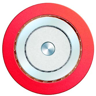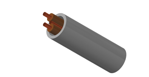
FLP300-VV-U/R Series Cable is a PVC-insulated and sheathed power cable that complies with international standards and offers comprehensive performance, specifically designed for stable and safe power transmission.
The product strictly adheres to the basic design standard of BS 6004:2012, with flame retardant performance passing the EN 60332-1-2 single vertical burning test. Boasting a voltage rating of 300/500V, it is widely applicable to various fixed installation scenarios such as building electrical systems, industrial wiring, and civil facilities, providing efficient and reliable power connection for your electrical system.
Basic design to BS 6004:2012
| Flame Retardance (Single Vertical Wire Test) | EN 60332-1-2 |
300/500V
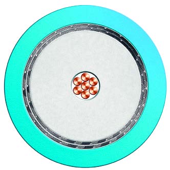
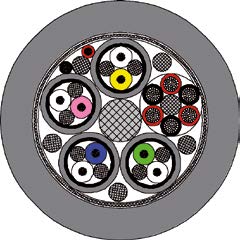
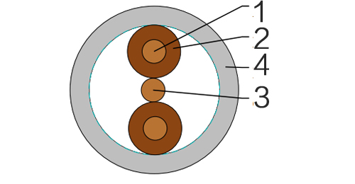
| Conductor | Annealed copper conductor,class 1 (1.0mm² to 2.5mm²) or class 2 (4mm² to 35mm²) according to BS EN 60228. |
| Insulation | PVC Type TI 1 according to BS EN 50363-3. |
| Circuit Protective Conductor (CPC) | Annealed plain copper (class 1 or 2) |
| Position of CPC | Centrally placed between cores in same plane (twin); centrally placed between black and grey cores in same plane(3-core). |
| Outer Sheath | PVC Type 6 according to BS 7655-4.2. |
| Outer Sheath Option | UV resistance,hydrocarbon resistance,oil resistance,anti rodent and anti termite properties can be offered as option. Compliance to fire performance standard (IEC 60332-1,IEC 60332-3,UL 1581,UL 1666 etc) depends on the oxygen index of the PVC compound and the overall cable design. LSPVC can also be provided upon request. |
Insulation Colour :
Twin : brown and blue, alternatively, for 2 x 1.0 and 2 x 1.5 cables, brown and brown;
3-core : brown, black (centre core), and grey
Sheath Colour : Grey, other colours can be offered upon request.
| Maximum temperature range during operation (PVC) | 70°C |
| Maximum short circuit temperature (5 Seconds) | 160°C |
| Minimum bending radius | 6 x Overall Diameter |
| Conductor | FLP300-VV-U/R | ||||||
|---|---|---|---|---|---|---|---|
| No. of Cores x Cross Section | Class of Conductor | Nominal Insulation Thickness | Cross-Section Area of CPC | Class of CPC | Nominal Sheath Thickness | Maximum Overall Diameter | Approx. Weight |
| No.xmm² | mm | mm² | mm | mm | kg/km | ||
| 2x1.0 | 1 | 0.6 | 1.0 | 1 | 0.9 | 4.8x8.7 | 68 |
| 2x1.5 | 1 | 0.7 | 1.0 | 1 | 0.9 | 5.3x9.7 | 85 |
| 2x2.5 | 1 | 0.8 | 1.5 | 1 | 1.0 | 6.2x11.7 | 120 |
| 2x4.0 | 2 | 0.8 | 1.5 | 1 | 1.0 | 6.9x13.1 | 175 |
| 2x6.0 | 2 | 0.8 | 2.5 | 1 | 1.1 | 7.8x15.0 | 240 |
| 2x10 | 2 | 1.0 | 4.0 | 2 | 1.2 | 9.5x18.9 | 390 |
| 2x16 | 2 | 1.0 | 6.0 | 2 | 1.3 | 10.8x21.9 | 560 |
| 3x1.0 | 1 | 0.6 | 1.0 | 1 | 0.9 | 4.8x11.4 | 91 |
| 3x1.5 | 1 | 0.7 | 1.0 | 1 | 0.9 | 5.3x12.9 | 115 |
| 3x2.5 | 1 | 0.8 | 1.5 | 1 | 1.0 | 6.2x15.3 | 170 |
| 3x4.0 | 2 | 0.8 | 1.5 | 1 | 1.1 | 7.1x17.9 | 250 |
| 3x6.0 | 2 | 0.8 | 2.5 | 1 | 1.1 | 7.8x20.2 | 340 |
| 3x10 | 2 | 1.0 | 4.0 | 2 | 1.2 | 9.5x25.7 | 540 |
| 3x16 | 2 | 1.0 | 6.0 | 2 | 1.3 | 10.8x29.7 | 790 |
| Conductor Operating Temperature | 70°C |
| Ambient Temperature | 30°C |
| Conductor cross-sectional area | Reference Method 100# (above a plasterboard ceiling covered by thermal insulation not exceeding 100 mm in thickness) | Reference Method 101# (above a plasterboard ceiling covered by thermal insulation exceeding 100 mm in thickness) | Reference Method 102# (in a stud wall with thermal insulation with cable touching the inner wall surface) | Reference Method 103# (in a stud wall with thermal insulation with cable not touching the inner wall surface) | Reference Method C* (clipped direct) | Reference Method A* (enclosed in conduit in an insulated wall) | Voltage Drop (per ampere per meter) |
|---|---|---|---|---|---|---|---|
| 1 | 2 | 3 | 4 | 5 | 6 | 7 | 8 |
| mm² | A | A | A | A | A | A | mV/A/m |
| 1.0 | 13 | 10.5 | 13 | 8.0 | 16 | 11.5 | 44 |
| 1.5 | 16 | 13 | 16 | 10 | 20 | 14.5 | 29 |
| 2.5 | 21 | 17 | 21 | 13.5 | 27 | 20 | 18 |
| 4.0 | 27 | 22 | 27 | 17.5 | 37 | 26 | 11 |
| 6.0 | 34 | 27 | 35 | 23.5 | 47 | 32 | 7.3 |
| 10 | 45 | 36 | 47 | 32 | 64 | 44 | 4.4 |
| 16 | 57 | 46 | 63 | 42.5 | 85 | 57 | 2.8 |
A* For full installation method refer to Table 4A2 (BS 7671-2008) Installation Method 2 but for flat twin and earth cable
C* For full installation method refer to Table 4A2 (BS 7671-2008) Installation Method 20 but for flat twin and earth cable
100# For full installation method refer to Table 4A2 (BS 7671-2008) Installation Method 100
102# For full installation method refer to Table 4A2 (BS 7671-2008) Installation Method 102
103# For full installation method refer to Table 4A2 (BS 7671-2008) Installation Method 103
Wherever practicable, a cable is to be fixed in a position such that it will not be covered with thermal insulation.
Regulation 523.7, BS 5803-5 Appendix C: Avoidance of overheating of electric cables, Building Regulations Approved document B and Thermal insulation: avoiding risks, BR 262, BRE, 2001 refer.