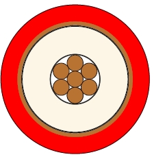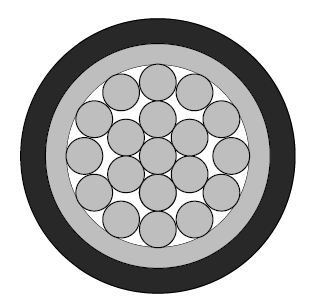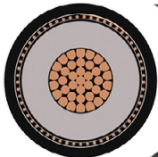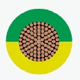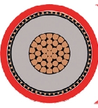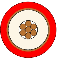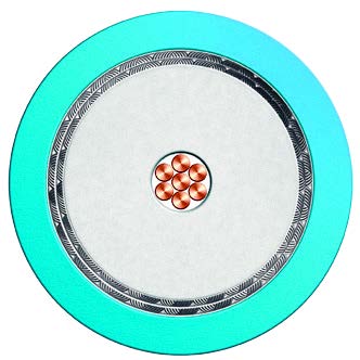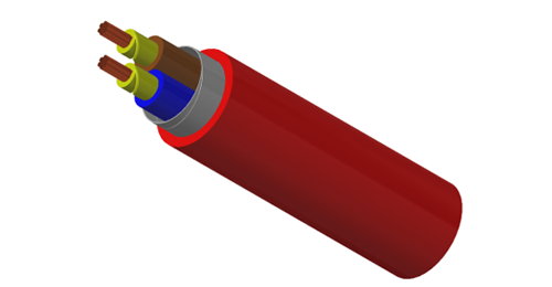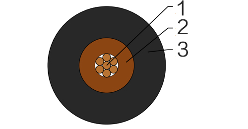
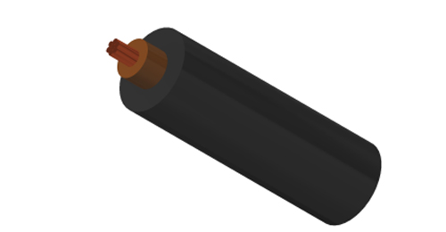
600/1000V single core PVC insulated PVC sheathed unarmoured cable is designed for fixed low voltage power distribution.
It is suitable for industrial plants, commercial buildings, control panels, distribution boards and general electrical installations.
The PVC insulation provides reliable electrical insulation for low voltage power circuits.
The PVC outer sheath provides general protection for fixed installation environments.
As an unarmoured cable, it does not provide metallic mechanical protection.
It is suitable for cable tray, conduit, trunking, duct and other protected cable routes.
It is not recommended for direct burial without additional mechanical protection.
The cable should be selected according to voltage rating, conductor size, conductor material, installation method and project specification.
Basic design to to IEC 60502-1
| Flame Retardance (Single Vertical Wire Test) | IEC 60332-1-2 |
600/1000V
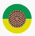
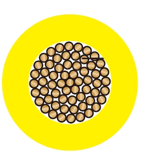
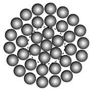
| Conductor | Plain annealed copper, stranded according to IEC 60228 class 2. |
| Insulation | PVC/A according to IEC 60502-1. |
| Outer Sheath | Extruded PVC Type ST1/ST2 according to IEC 60502-1. |
| Outer Sheath Option | UV resistance, hydrocarbon resistance, oil resistance, anti rodent and anti termite properties can be offered as option. Compliance to fire performance standard (IEC 60332-1, IEC 60332-3, UL 1581, UL 1666 etc) depends on the oxygen index of the PVC compound and the overall cable design. LSPVC can also be provided upon request. |
| Insulation Colour | Brown or blue, other colours can be offered upon request. |
| Sheath Colour | Black, other colours can be offered upon request. |
| Maximum temperature range during operation | 70°C |
| Maximum short circuit temperature (5 Seconds) | |
| Conductor cross-section ≤300 mm²160°C Conductor cross-section >300 mm²140°C | |
| Minimum bending radius | |
| Circular copper conductor (OD ≤ 25mm)4 x Overall Diameter Circular copper conductor (OD > 25mm)6 x Overall Diameter Shaped copper conductor8 x Overall Diameter | |
| Conductor | FLP600-RV-R | ||||
|---|---|---|---|---|---|
| No. of Cores xCross Section | Class of Conductor | Nominal Insulation Thickness | Nominal Sheath Thickness | Nominal Overall Diameter | Approx. Weight |
| No.xmm2 | mm | mm | mm | kg/km | |
| 1x1.5 | 2 | 0.8 | 1.4 | 5.8 | 55 |
| 1x2.5 | 2 | 0.8 | 1.4 | 6.2 | 70 |
| 1x4.0 | 2 | 1 | 1.4 | 7.1 | 98 |
| 1x6.0 | 2 | 1 | 1.4 | 7.6 | 124 |
| 1x10 | 2 | 1 | 1.4 | 8.4 | 173 |
| 1x16 | 2 | 1 | 1.4 | 9.3 | 240 |
| 1x25 | 2 | 1.2 | 1.4 | 10.8 | 350 |
| 1x35 | 2 | 1.2 | 1.4 | 11.9 | 468 |
| 1x50 | 2 | 1.4 | 1.4 | 13.6 | 646 |
| 1x70 | 2 | 1.4 | 1.4 | 15 | 854 |
| 1x95 | 2 | 1.6 | 1.5 | 17.2 | 1154 |
| 1x120 | 2 | 1.6 | 1.5 | 18.6 | 1428 |
| 1x150 | 2 | 1.8 | 1.6 | 20.6 | 1764 |
| 1x185 | 2 | 2 | 1.7 | 22.7 | 2160 |
| 1x240 | 2 | 2.2 | 1.8 | 25.5 | 2796 |
| 1x300 | 2 | 2.4 | 1.9 | 28.1 | 3449 |
| 1x400 | 2 | 2.6 | 2 | 31.8 | 4570 |
| 1x500 | 2 | 2.8 | 2.1 | 35 | 5641 |
| 1x630 | 2 | 2.8 | 2.2 | 38.3 | 7015 |
| 1x800 | 2 | 2.8 | 2.3 | 42.1 | 8798 |
| 1x1000 | 2 | 3 | 2.5 | 46.7 | 10970 |
| Conductor Operating Temperature | 70°C |
| Ambient Temperature | 30°C |
| Conductor cross-sectional area | Reference Method A (enclosed in conduit in thermally insulating wall etc) | Reference Method B (enclosed in conduit on a wall or in trunking etc) | Reference Method C (clipped direct) | Reference Method F (in free air or on a perforated cable tray horizontal or vertical etc) | |||||||
|---|---|---|---|---|---|---|---|---|---|---|---|
| 2cables, single-phase a.c. or d.c. | 3 or 4 cables, three-phase a.c. | 2 cables, single-phase a.c. or d.c | 3 or 4 cables, three-phase a.c. | 2 cables, single-phase a.c. or d.c. flat and touching | 3 or 4 cables, three-phase a.c. flat and touching or trefoil | 2 cables, single-phase a.c. or d.c. flat | 3 cables, three-phase a.c. flat | 3 cables, three-phase a.c. trefoil | 2 cables, single-phase a.c. or d.c. or 3 cables three-phase a.c. flat | ||
| Horizontal | Vertical | ||||||||||
| 1 | 2 | 3 | 4 | 5 | 6 | 7 | 8 | 9 | 10 | 11 | 12 |
| mm² | A | A | A | A | A | A | A | A | A | A | A |
| 1 | 11 | 10.5 | 13.5 | 12 | 15.5 | 14 | - | - | - | - | - |
| 1.5 | 14.5 | 13.5 | 17.5 | 15.5 | 20 | 18 | - | - | - | - | - |
| 2.5 | 20 | 18 | 24 | 21 | 27 | 25 | - | - | - | - | - |
| 4 | 26 | 24 | 32 | 28 | 37 | 33 | - | - | - | - | - |
| 6 | 34 | 31 | 41 | 36 | 47 | 43 | - | - | - | - | - |
| 10 | 46 | 42 | 57 | 50 | 65 | 59 | - | - | - | - | - |
| 16 | 61 | 56 | 76 | 68 | 87 | 79 | - | - | - | - | - |
| 25 | 80 | 73 | 101 | 89 | 114 | 104 | 131 | 114 | 110 | 146 | 130 |
| 35 | 99 | 89 | 125 | 110 | 141 | 129 | 162 | 143 | 137 | 181 | 162 |
| 50 | 119 | 108 | 151 | 134 | 182 | 167 | 196 | 174 | 167 | 219 | 197 |
| 70 | 151 | 136 | 192 | 171 | 234 | 214 | 251 | 225 | 216 | 281 | 254 |
| 95 | 182 | 164 | 232 | 207 | 284 | 261 | 304 | 275 | 264 | 341 | 311 |
| 120 | 210 | 188 | 269 | 239 | 330 | 303 | 352 | 321 | 308 | 396 | 362 |
| 150 | 240 | 216 | 300 | 262 | 381 | 349 | 406 | 372 | 356 | 456 | 419 |
| 185 | 273 | 245 | 341 | 296 | 436 | 400 | 463 | 427 | 409 | 521 | 480 |
| 240 | 321 | 286 | 400 | 346 | 515 | 472 | 546 | 507 | 485 | 615 | 569 |
| 300 | 367 | 328 | 458 | 394 | 594 | 545 | 629 | 587 | 561 | 709 | 659 |
| 400 | - | - | 546 | 467 | 694 | 634 | 754 | 689 | 656 | 852 | 795 |
| 500 | - | - | 626 | 533 | 792 | 723 | 868 | 789 | 749 | 982 | 920 |
| 630 | - | - | 720 | 611 | 904 | 826 | 1005 | 905 | 855 | 1138 | 1070 |
| 800 | - | - | - | - | 1030 | 943 | 1086 | 1020 | 971 | 1265 | 1188 |
| 1000 | - | - | - | - | 1154 | 1058 | 1216 | 1149 | 1079 | 1420 | 1337 |
| Nominal Cross Section Area | 2 cables d.c. | 2 cables, single-phase a.c. | 3 or 4 cables, three-phase a.c. | |||||||||||||||||||
|---|---|---|---|---|---|---|---|---|---|---|---|---|---|---|---|---|---|---|---|---|---|---|
| Ref. Methods A and B (enclosed in conduit or trunking) | Ref. Methods C & F(clipped direct, on trays or in free air) | Ref. Methods A & B (enclosed in conduit or trunking | Ref. Methods C & F(clipped direct, on trays or in free air) | |||||||||||||||||||
| Cables touching | Cables spaced* | Cables touching, Trefoil | Cables touching, Flat | Cables spaced*, Flat | ||||||||||||||||||
| 1 | 2 | 3 | 4 | 5 | 6 | 7 | 8 | 9 | ||||||||||||||
| mm² | mV/A/m | |||||||||||||||||||||
| 1 | 44 | 44 | 44 | 44 | 38 | 38 | 38 | 38 | ||||||||||||||
| 1.5 | 29 | 29 | 29 | 29 | 25 | 25 | 25 | 25 | ||||||||||||||
| 2.5 | 18 | 18 | 18 | 18 | 15 | 15 | 15 | 15 | ||||||||||||||
| 4 | 11 | 11 | 11 | 11 | 9.5 | 9.5 | 9.5 | 9.5 | ||||||||||||||
| 6 | 7.3 | 7.3 | 7.3 | 7.3 | 6.4 | 6.4 | 6.4 | 6.4 | ||||||||||||||
| 10 | 4.4 | 4.4 | 4.4 | 4.4 | 3.8 | 3.8 | 3.8 | 3.8 | ||||||||||||||
| 16 | 2.8 | 2.8 | 2.8 | 2.8 | 2.4 | 2.4 | 2.4 | 2.4 | ||||||||||||||
| r | x | z | r | x | z | r | x | z | r | x | z | r | x | z | r | x | z | r | x | z | ||
| 25 | 1.75 | 1.8 | 0.33 | 1.8 | 1.75 | 0.2 | 1.75 | 1.75 | 0.29 | 1.8 | 1.5 | 0.29 | 1.55 | 1.5 | 0.175 | 1.5 | 1.5 | 0.25 | 1.55 | 1.5 | 0.32 | 1.55 |
| 35 | 1.25 | 1.3 | 0.31 | 1.3 | 1.25 | 0.195 | 1.25 | 1.25 | 0.28 | 1.3 | 1.1 | 0.27 | 1.1 | 1.1 | 0.17 | 1.1 | 1.1 | 0.24 | 1.1 | 1.1 | 0.32 | 1.15 |
| 50 | 0.93 | 0.95 | 0.3 | 1 | 0.93 | 0.19 | 0.95 | 0.93 | 0.28 | 0.97 | 0.81 | 0.26 | 0.85 | 0.8 | 0.165 | 0.82 | 0.8 | 0.24 | 0.84 | 0.8 | 0.32 | 0.86 |
| 70 | 0.63 | 0.65 | 0.29 | 0.72 | 0.63 | 0.185 | 0.66 | 0.63 | 0.27 | 0.69 | 0.56 | 0.25 | 0.61 | 0.55 | 0.16 | 0.57 | 0.55 | 0.24 | 0.6 | 0.55 | 0.31 | 0.63 |
| 95 | 0.46 | 0.49 | 0.28 | 0.56 | 0.47 | 0.18 | 0.5 | 0.47 | 0.27 | 0.54 | 0.42 | 0.24 | 0.48 | 0.41 | 0.155 | 0.43 | 0.41 | 0.23 | 0.47 | 0.4 | 0.31 | 0.51 |
| 120 | 0.36 | 0.39 | 0.27 | 0.47 | 0.37 | 0.175 | 0.41 | 0.37 | 0.26 | 0.45 | 0.33 | 0.23 | 0.41 | 0.32 | 0.15 | 0.36 | 0.32 | 0.23 | 0.4 | 0.32 | 0.3 | 0.44 |
| 150 | 0.29 | 0.31 | 0.27 | 0.41 | 0.3 | 0.175 | 0.34 | 0.29 | 0.26 | 0.39 | 0.27 | 0.23 | 0.36 | 0.26 | 0.15 | 0.3 | 0.26 | 0.23 | 0.34 | 0.26 | 0.3 | 0.4 |
| 185 | 0.23 | 0.25 | 0.27 | 0.37 | 0.24 | 0.17 | 0.29 | 0.24 | 0.26 | 0.35 | 0.22 | 0.23 | 0.32 | 0.21 | 0.145 | 0.26 | 0.21 | 0.22 | 0.31 | 0.21 | 0.3 | 0.36 |
| 240 | 0.18 | 0.195 | 0.26 | 0.33 | 0.185 | 0.165 | 0.25 | 0.185 | 0.25 | 0.31 | 0.17 | 0.23 | 0.29 | 0.16 | 0.145 | 0.22 | 0.16 | 0.22 | 0.27 | 0.16 | 0.29 | 0.34 |
| 300 | 0.145 | 0.16 | 0.26 | 0.31 | 0.15 | 0.165 | 0.22 | 0.15 | 0.25 | 0.29 | 0.14 | 0.23 | 0.27 | 0.13 | 0.14 | 0.19 | 0.13 | 0.22 | 0.25 | 0.13 | 0.29 | 0.32 |
| 400 | 0.105 | 0.13 | 0.26 | 0.29 | 0.12 | 0.16 | 0.2 | 0.115 | 0.25 | 0.27 | 0.12 | 0.22 | 0.25 | 0.105 | 0.14 | 0.175 | 0.105 | 0.21 | 0.24 | 0.1 | 0.29 | 0.31 |
| 500 | 0.086 | 0.11 | 0.26 | 0.28 | 0.098 | 0.155 | 0.185 | 0.093 | 0.24 | 0.26 | 0.1 | 0.22 | 0.25 | 0.086 | 0.135 | 0.16 | 0.086 | 0.21 | 0.23 | 0.081 | 0.29 | 0.3 |
| 630 | 0.068 | 0.094 | 0.25 | 0.27 | 0.081 | 0.155 | 0.175 | 0.076 | 0.24 | 0.25 | 0.08 | 0.22 | 0.24 | 0.072 | 0.135 | 0.15 | 0.072 | 0.21 | 0.22 | 0.066 | 0.28 | 0.29 |
| 800 | 0.053 | - | - | - | 0.068 | 0.15 | 0.165 | 0.061 | 0.24 | 0.25 | - | - | - | 0.06 | 0.13 | 0.145 | 0.06 | 0.21 | 0.22 | 0.053 | 0.28 | 0.29 |
| 1000 | 0.042 | - | - | - | 0.059 | 0.15 | 0.16 | 0.05 | 0.24 | 0.24 | - | - | - | 0.052 | 0.13 | 0.14 | 0.052 | 0.2 | 0.21 | 0.044 | 0.28 | 0.28 |
Note: *Spacings larger than one cable diameter will result in a large voltage drop.
r = conductor resistance at operating temperature
x = reactance
z = impedance
KEY FEATURES
- Manufactured according to IEC 60502-1 requirements
- 600/1000V voltage rating
- Single core power cable construction
- PVC insulated conductor
- PVC outer sheath
- Unarmoured cable design
- Suitable for fixed low voltage power distribution
- Suitable for cable tray, conduit and trunking
- Suitable for industrial and commercial installations
- Commonly used in protected cable routes
SELECTION NOTES
Before quotation, please confirm:
- Voltage rating
- Conductor size
- Conductor material
- Cable length
- Sheath colour
- Installation method
- Installation environment
- Required standard or project specification
- Packing requirement
- Destination port or delivery address
600/1000V single core PVC unarmoured cable is commonly selected for fixed low voltage power distribution.
It is suitable where mechanical protection is provided by the installation system.
RELATED CABLE TYPES
- IEC 60502 low voltage cable
- PVC insulated PVC sheathed cable
- PVC unarmoured power cable
- XLPE insulated PVC sheathed unarmoured cable
- XLPE PVC armoured cable
- PVC armoured power cable
- BS7889 unarmoured power cable
- 600/1000V power cable
- Low voltage power cable
- Fixed installation cable
FAQ
What is this cable used for?
It is used for fixed low voltage power distribution.
It is suitable for industrial plants, commercial buildings, panels and protected cable routes.
What standard does this cable follow?
This cable is designed according to IEC 60502-1 requirements.
Is this cable armoured?
No. This is an unarmoured cable.
It does not have metallic armour protection.
Can this cable be used underground?
It is not recommended for direct burial without additional mechanical protection.
For underground use, the installation method should follow the project specification.
What is the difference between armoured and unarmoured cable?
Armoured cable has metallic armour for mechanical protection.
Unarmoured cable is normally used in protected routes such as tray, conduit or trunking.
What information is required for quotation?
Please confirm voltage rating, conductor size, conductor material and cable length.
Installation method and destination port are also required.
Can BURYCABLE supply IEC 60502 single core unarmoured cable?
Yes. BURYCABLE can supply IEC 60502-1 single core PVC insulated PVC sheathed unarmoured cables.
We can support different conductor sizes, sheath colours, lengths and packing requirements.