APPLICATION
This series of cables is specifically designed for critical facilities with extremely high requirements for safety and reliability. It is widely used in power plants, underground rail transit systems, airports, petrochemical facilities, star-rated hotels, medical institutions, and high-rise buildings, providing a robust guarantee for stable power supply in various demanding environments.
STANDARDS
The product strictly adheres to the IEC 60502-1 international standard for fundamental design and manufacturing.
FIRE PERFORMANCE
| Flame Retardance (Single Vertical Wire Test) | IEC 60332-1 |
VOLTAGE RATING
600/1000V
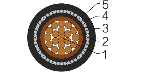
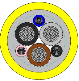
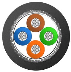
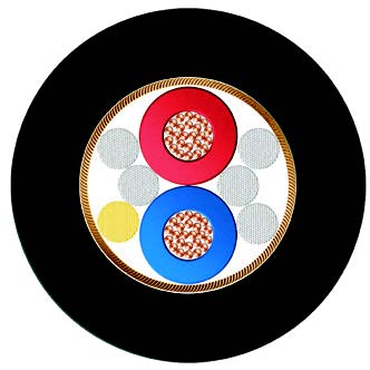
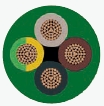
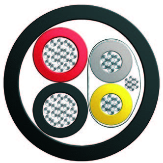
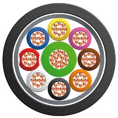
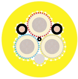
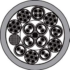
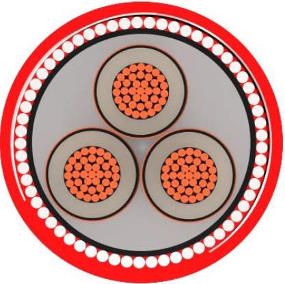
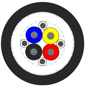
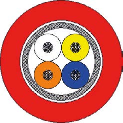
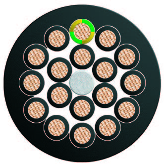
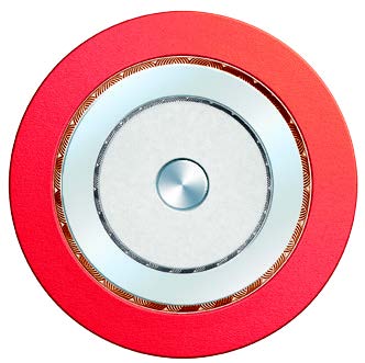
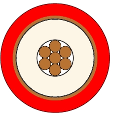
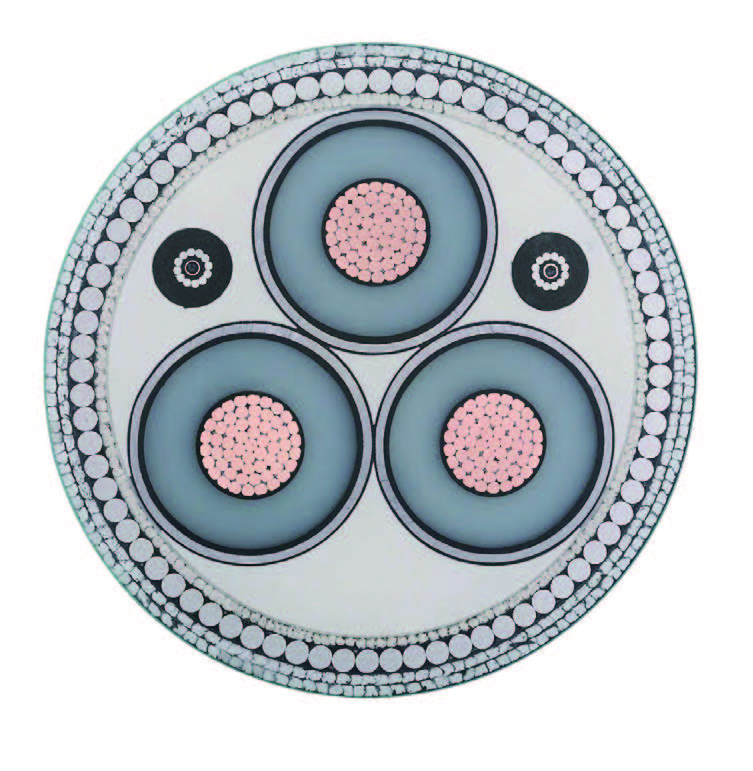
CABLE CONSTRUCTION
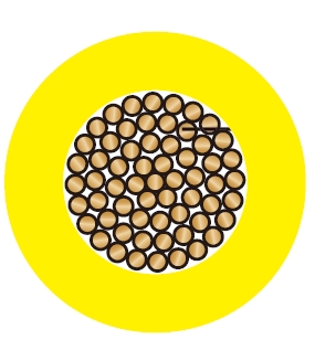
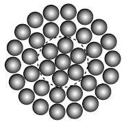
| Conductor | Annealed copper wire, stranded according to IEC 60228 class 2. |
| Insulation | XLPE according to IEC 60502-1. |
| Inner Covering | Extruded PVC or polymeric compound. |
| Armouring | Aluminium wire |
| Outer Sheath | Extruded PVC Type ST1/ST2 according to IEC 60502-1. |
| Outer Sheath Option | UV resistance, hydrocarbon resistance, oil resistance, anti rodent and anti termite properties can be offered as option. Compliance to fire performance standard (IEC 60332-1, IEC 60332-3, UL 1581, UL 1666 etc) depends on the oxygen index of the PVC compound and the overall cable design. LSPVC can also be provided upon request. |
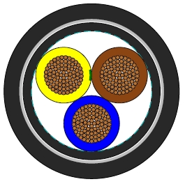
COLOUR CODE
| Insulation Colour | Brown or blue, other colours can be offered upon request. |
| Sheath Colour | Black, other colours can be offered upon request. |
MECHANICAL AND ELECTRICAL PROPERTIES
| Maximum temperature range during operation | 80°C (For ST1 Sheath); 90°C (For ST2 Sheath) |
| Maximum short circuit temperature (5 Seconds) | 250°C |
| Minimum bending radius |
| Circular copper conductors | 6 x Overall Diameter |
| Shaped copper conductors | 8 x Overall Diameter |
CONSTRUCTION PARAMETERS
| Conductor | FLP600-RVMAV-R |
|---|
| No. of Cores × Cross Section | Class of Conductor | Nominal Insulation Thickness | Nominal Inner Covering Thickness | Nominal Armour Wire Diameter | Nominal Sheath Thickness | Approx. Overall Diameter | Approx. Weight |
|---|
| No.xmm² | | mm | mm | mm | mm | mm | kg/km |
|---|
| 1x1.5 | 2 | 0.7 | 1.0 | 0.8 | 1.8 | 10.2 | 150 |
| 1x2.5 | 2 | 0.7 | 1.0 | 0.8 | 1.8 | 10.6 | 169 |
| 1x4.0 | 2 | 0.7 | 1.0 | 0.8 | 1.8 | 11.2 | 196 |
| 1x6.0 | 2 | 0.7 | 1.0 | 0.8 | 1.8 | 11.7 | 228 |
| 1x10 | 2 | 0.7 | 1.0 | 0.8 | 1.8 | 12.7 | 290 |
| 1x16 | 2 | 0.7 | 1.0 | 0.8 | 1.8 | 13.7 | 372 |
| 1x25 | 2 | 0.9 | 1.0 | 0.8 | 1.8 | 15.4 | 507 |
| 1x35 | 2 | 0.9 | 1.0 | 1.25 | 1.8 | 17.5 | 681 |
| 1x50 | 2 | 1.0 | 1.0 | 1.25 | 1.8 | 19.0 | 848 |
| 1x70 | 2 | 1.1 | 1.0 | 1.25 | 1.8 | 21.0 | 1116 |
| 1x95 | 2 | 1.1 | 1.0 | 1.6 | 1.8 | 24.0 | 1511 |
| 1x120 | 2 | 1.2 | 1.0 | 1.6 | 1.8 | 25.8 | 1821 |
| 1x150 | 2 | 1.4 | 1.0 | 1.6 | 1.8 | 27.8 | 2165 |
| 1x185 | 2 | 1.6 | 1.0 | 1.6 | 1.8 | 30.4 | 2655 |
| 1x240 | 2 | 1.7 | 1.0 | 1.6 | 1.9 | 33.5 | 3352 |
| 1x300 | 2 | 1.8 | 1.0 | 2.0 | 2.0 | 37.5 | 4224 |
| 1x400 | 2 | 2.0 | 1.2 | 2.0 | 2.2 | 41.3 | 5263 |
| 1x500 | 2 | 2.2 | 1.2 | 2.0 | 2.3 | 44.2 | 7379 |
| 1x630 | 2 | 2.4 | 1.2 | 2.5 | 2.4 | 49.8 | 9611 |
| 1x800 | 2 | 2.6 | 1.4 | 2.5 | 2.6 | 55.3 | 11896 |
| 1x1000 | 2 | 2.8 | 1.4 | 2.5 | 2.7 | 60.4 | 14467 |
ELECTRICAL PROPERTIES
| Conductor Operating Temperature | 90°C |
| Ambient Temperature | 30°C |
Current-Carrying Capacities (Amp) according to BS 7671: 2008 table 4E3A
| Conductor cross-sectional area | Reference Method C (clipped direct) | Reference Method F (in free air or on a perforated cable tray, horizontal or vertical) |
|---|
| Touching | Touching | Spaced by on cable diameter |
|---|
| 2 cables, single-phase a.c. or d.c. flat | 3 or 4 cables, threep-hase a.c. flat | 2 cables, single-phase a.c. or d.c. flat | 3 or 4 cables, three-phase a.c. flat | 3 cables threep-hase a.c. trefoil | 2 cables, d.c. | 2 cables, single-phase a.c. | 3 or 4 cables, three-phase a.c. |
|---|
| Horizontal | Vertical | Horizontal | Vertical | Horizontal | Vertical |
|---|
| 1 | 2 | 3 | 4 | 5 | 6 | 7 | 8 | 9 | 10 | 11 | 12 |
|---|
| mm2 | A | A | A | A | A | A | A | A | A | A | A |
|---|
| 50 | 237 | 220 | 253 | 232 | 222 | 284 | 270 | 282 | 266 | 288 | 266 |
| 70 | 303 | 277 | 322 | 293 | 285 | 356 | 349 | 357 | 337 | 358 | 331 |
| 95 | 367 | 333 | 389 | 352 | 346 | 446 | 426 | 436 | 412 | 425 | 393 |
| 120 | 425 | 383 | 449 | 405 | 402 | 519 | 497 | 504 | 477 | 485 | 449 |
| 150 | 488 | 437 | 516 | 462 | 463 | 600 | 575 | 566 | 539 | 549 | 510 |
| 185 | 557 | 496 | 587 | 524 | 529 | 688 | 660 | 643 | 614 | 618 | 574 |
| 240 | 656 | 579 | 689 | 612 | 625 | 815 | 782 | 749 | 714 | 715 | 666 |
| 300 | 755 | 662 | 792 | 700 | 720 | 943 | 906 | 842 | 805 | 810 | 755 |
| 400 | 853 | 717 | 899 | 767 | 815 | 1137 | 1094 | 929 | 889 | 848 | 797 |
| 500 | 962 | 791 | 1016 | 851 | 918 | 1314 | 1266 | 1032 | 989 | 923 | 871 |
| 630 | 1082 | 861 | 1146 | 935 | 1027 | 1528 | 1474 | 1139 | 1092 | 992 | 940 |
| 800 | 1170 | 904 | 1246 | 987 | 1119 | 1809 | 1744 | 1204 | 1155 | 1042 | 978 |
| 1000 | 1261 | 961 | 1345 | 1055 | 1214 | 2100 | 2026 | 1289 | 1238 | 1110 | 1041 |
Voltage Drop (Per Amp Per Meter) according to BS 7671: 2008 table 4E3B
| Nominal Cross Section Area | 2 cables d.c. | Ref. Methods C&F(clipped direct, on trays or in free air) |
|---|
| 2 cables, single-phase a.c. | 3 or 4 cables, three-phase a.c. |
|---|
| Touching | Spaced* | Trefoil and touching | Flat and touching | Flat and spaced* |
|---|
| 1 | 2 | 3 | 4 | 5 | 6 | 7 |
|---|
| mm2 | mV/A/m | mV/A/m | mV/A/m | mV/A/m | mV/A/m | mV/A/m |
|---|
|
| r | x | z | r | x | z | r | x | z | r | x | z | r | x | z |
| 50 | 0.98 | 0.99 | 0.21 | 1.0 | 0.98 | 0.29 | 1.0 | 0.86 | 0.18 | 0.87 | 0.64 | 0.25 | 0.88 | 0.84 | 0.33 | 0.9 |
| 70 | 0.67 | 0.68 | 0.20 | 0.71 | 0.69 | 0.29 | 0.75 | 0.59 | 0.170 | 0.62 | 0.60 | 0.25 | 0.65 | 0.62 | 0.32 | 0.70 |
| 95 | 0.49 | 0.51 | 0.195 | 0.55 | 0.53 | 0.28 | 0.60 | 0.44 | 0.170 | 0.47 | 0.46 | 0.24 | 0.52 | 0.49 | 0.31 | 0.58 |
| 120 | 0.39 | 0.41 | 0.190 | 0.45 | 0.43 | 0.27 | 0.51 | 0.35 | 0.165 | 0.39 | 0.38 | 0.24 | 0.44 | 0.41 | 0.30 | 0.51 |
| 150 | 0.31 | 0.33 | 0.185 | 0.38 | 0.36 | 0.27 | 0.45 | 0.29 | 0.160 | 0.33 | 0.31 | 0.23 | 0.39 | 0.34 | 0.29 | 0.45 |
| 185 | 0.25 | 0.27 | 0.185 | 0.33 | 0.30 | 0.26 | 0.40 | 0.23 | 0.160 | 0.28 | 0.26 | 0.23 | 0.34 | 0.29 | 0.29 | 0.41 |
| 240 | 0.195 | 0.21 | 0.180 | 0.28 | 0.24 | 0.26 | 0.35 | 0.180 | 0.155 | 0.24 | 0.21 | 0.22 | 0.30 | 0.24 | 0.28 | 0.37 |
| 300 | 0.155 | 0.17 | 0.175 | 0.25 | 0.195 | 0.25 | 0.32 | 0.145 | 0.150 | 0.21 | 0.170 | 0.22 | 0.28 | 0.20 | 0.27 | 0.34 |
| 400 | 0.115 | 0.145 | 0.170 | 0.22 | 0.180 | 0.24 | 0.30 | 0.125 | 0.150 | 0.195 | 0.160 | 0.21 | 0.27 | 0.20 | 0.27 | 0.33 |
| 500 | 0.093 | 0.125 | 0.170 | 0.21 | 0.165 | 0.24 | 0.29 | 0.105 | 0.145 | 0.180 | 0.145 | 0.20 | 0.25 | 0.190 | 0.24 | 0.31 |
| 630 | 0.073 | 0.105 | 0.165 | 0.195 | 0.150 | 0.23 | 0.27 | 0.092 | 0.145 | 0.170 | 0.135 | 0.195 | 0.24 | 0.175 | 0.23 | 0.29 |
| 800 | 0.056 | 0.090 | 0.160 | 0.190 | 0.145 | 0.23 | 0.27 | 0.086 | 0.140 | 0.165 | 0.130 | 0.180 | 0.23 | 0.175 | 0.195 | 0.26 |
| 1000 | 0.045 | 0.092 | 0.155 | 0.180 | 0.140 | 0.21 | 0.25 | 0.080 | 0.135 | 0.155 | 0.125 | 0.170 | 0.21 | 0.165 | 0.180 | 0.24 |
Note: *Spacings larger than one cable diameter will result in a large voltage drop.
r = conductor resistance at operating temperature
x = reactance
z = impedance