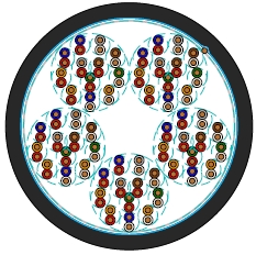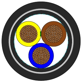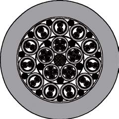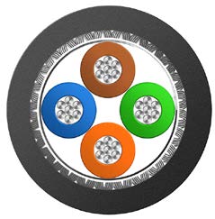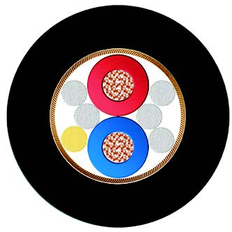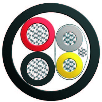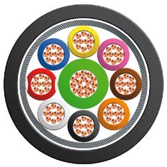
P34 BFOU-HCF 0.6/1 kV Marine Power and Control Cable: A Reliable Choice for Extreme Environments
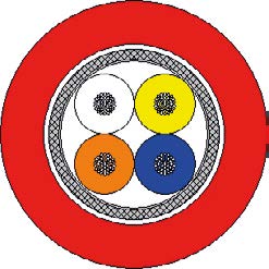
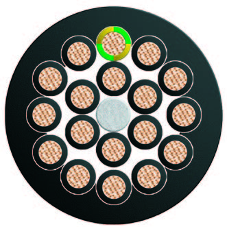
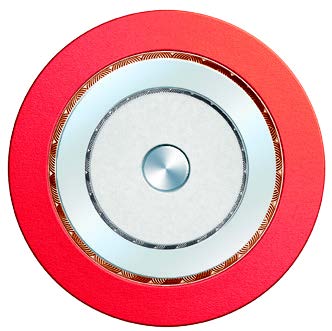
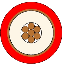
In harsh marine environments, the stable operation of power and control systems is critical. The P34 BFOU-HCF cable is a flame-retardant, fire-resistant, low-smoke, zero-halogen power and control cable specifically designed for offshore oil platforms, ships, and other marine facilities, complying with the NEK 606 standard.
IEC 60092-353
IEC 60092-351
IEC 60092-359
IEC 60331-21
IEC 60332-1
IEC 60332-3-22
IEC 60754-1,2
IEC 61034-1,2
NEK 606:2004
Electrical Characteristics
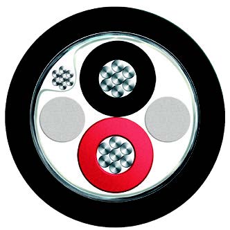
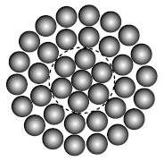
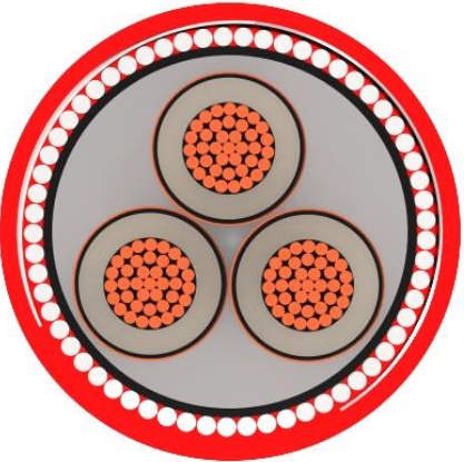
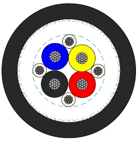
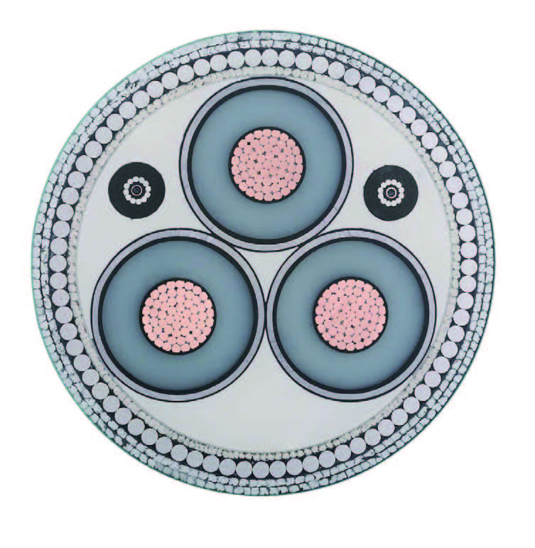
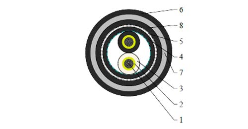
| Conductors | Tinned annealed stranded compacted copper to IEC 60228 class 2. |
| Insulation | Mica tape + Halogen free EPR/XLPE. |
| Bedding | Halogen free compound. |
| Armour | Tinned copper wire braid. |
| Outer Sheath1 | Halogen free thermosetting compound, SHF2. |
| HC-fire protection | Extruded thermoplastic fire protection compound. |
| Taping | Lapped glass fibre tape. |
| Outer Sheath2 | Flame retardant halogen-free thermoplastic compound, SHF1,coloured black. |
| Nominal Cross Section Area | mm^2 | 1.5 | 2.5 | 4 | 6 | 16 | 35 |
| Nominal Conductor Diameter | mm | 1.6 | 2.1 | 2.6 | 3.2 | 5.1 | 7.4 |
| Maximum DC Resistant@20℃ | Ω/km | 12.2 | 7.56 | 4.7 | 3.11 | 1.16 | 0.529 |
| Continuous Current Rating@45℃1 Core | A | 23 | 30 | 40 | 52 | 96 | 157 |
| Continuous Current Rating@45℃2 Core | A | 20 | 26 | 34 | 44 | 82 | 133 |
| Continuous Current Rating@45℃3&4 Core | A | 16 | 21 | 28 | 36 | 67 | 110 |
| Short Circuit Current 1s | A | 210 | 360 | 570 | 860 | 2290 | 5010 |
| Operating Voltage | KV | 0.6/1 | 0.6/1 | 0.6/1 | 0.6/1 | 0.6/1 | 0.6/1 |
| Nominal Cross Section Area | mm^2 | 50 | 70 | 95 | 120 | 150 | 185 | 240 | 300 |
| Nominal Conductor Diameter | mm | 8.7 | 10.3 | 12.2 | 13.8 | 15.1 | 17.0 | 19.6 | 21.9 |
| Maximum DC Resistant@20℃ | Ω/km | 0.391 | 0.27 | 0.195 | 0.154 | 0.126 | 0.1 | 0.0762 | 0.0607 |
| Continuous Current Rating@45℃1 Core | A | 196 | 242 | 293 | 339 | 389 | 444 | 522 | 601 |
| Continuous Current Rating@45℃2 Core | A | 167 | 206 | 249 | 288 | 331 | 444 | 444 | 511 |
| Continuous Current Rating@45℃3&4 Core | A | 137 | 169 | 205 | 237 | 272 | 311 | 365 | 421 |
| Short Circuit Current 1s | A | 7150 | 10020 | 13590 | 17170 | 21460 | 26470 | 34340 | 42930 |
| Operating Voltage | KV | 0.6/1 | 0.6/1 | 0.6/1 | 0.6/1 | 0.6/1 | 0.6/1 | 0.6/1 | 0.6/1 |
Note: For more than 4-cores, the current ratings may be calculated from the following formula (IN I1 / N 3 = ), I1= Current rating for 1-core, N = Number of cores.
| Ambient Temperature Correction Factors | 35 | 40 | 45 | 50 | 55 | 60 | 65 | 70 | 75 | 80 |
| Rating Factor | 1.1 | 1.05 | 1.0 | 0.94 | 0.88 | 0.82 | 0.74 | 0.67 | 0.58 | 0.47 |
| Bending Radius | 20×OD (during installation) |
| 12×OD (fixed installed) | |
| Temperature Range | -20℃ ~ +90℃ |
| Construction No. of cores×Cross section(mm^2) | Nominal Insulation Thickness (mm) | Nominal Diameter Over Bedding (mm) | Nominal Diameter Over Sheath1 (mm) | Nominal Overall Diameter (mm) | Nominal Weight (kg/km) |
| 1×50 | 1.4 | 15.0 | 18.5 | 45.5 | 2900 |
| 1×70 | 1.4 | 16.5 | 20.5 | 47.5 | 3300 |
| 1×95 | 1.6 | 18.5 | 23.0 | 50.5 | 3800 |
| 1×120 | 1.6 | 20.5 | 25.0 | 52.5 | 4260 |
| 1×150 | 1.8 | 23.0 | 27.0 | 54.5 | 4750 |
| 1×185 | 2.0 | 25.0 | 29.5 | 57.5 | 5380 |
| 1×240 | 2.2 | 28.0 | 32.5 | 66.0 | 7050 |
| 1×300 | 2.4 | 30.5 | 35.5 | 68.0 | 8000 |
| 2×1.5 | 1.0 | 10.0 | 13.0 | 40.5 | 1890 |
| 2×2.5 | 1.0 | 11.0 | 14.5 | 42.0 | 2080 |
| 3×1.5 | 1.0 | 10.5 | 14.0 | 42.0 | 2140 |
| 3×2.5 | 1.0 | 11.5 | 15.0 | 42.5 | 2200 |
| 3×4 | 1.0 | 13.0 | 16.5 | 43.0 | 2400 |
| 3×6 | 1.0 | 14.0 | 18.0 | 45.0 | 2600 |
| 3×16 | 1.0 | 18.5 | 23.0 | 50.0 | 3500 |
| 3×35 | 1.2 | 25.0 | 29.5 | 57.5 | 4840 |
| 3×70 | 1.4 | 33.0 | 39.0 | 72.0 | 8150 |
| 3×120 | 1.6 | 41.0 | 48.0 | 81.5 | 11300 |
| 3×150 | 1.8 | 46.0 | 54.5 | 88.5 | 13300 |
| 4×2.5 | 1.0 | 12.5 | 16.5 | 44.0 | 2300 |
| 4×6 | 1.0 | 15.5 | 19.5 | 47.5 | 2870 |
| 4×16 | 1.0 | 20.5 | 25.0 | 53.5 | 3830 |
| 7×1.5 | 1.0 | 14.0 | 17.5 | 44.5 | 2550 |
| 12×1.5 | 1.0 | 18.5 | 22.5 | 50.0 | 3140 |
| 27×1.5 | 1.0 | 26.5 | 31.0 | 64.5 | 5070 |
| 7×2.5 | 1.0 | 15.0 | 19.0 | 46.0 | 2760 |
| 12×2.5 | 1.0 | 20.5 | 24.5 | 52.0 | 3500 |
Note: For XLPE insulated cable, a thinner insulation thickness is applied.