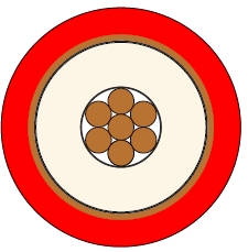
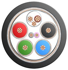
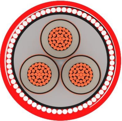
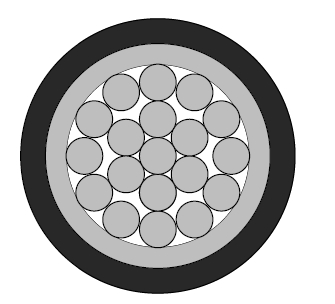
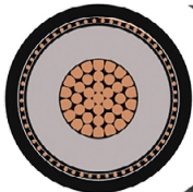
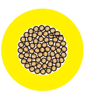
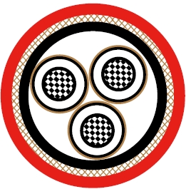
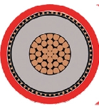
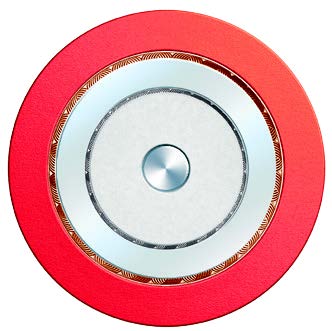
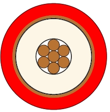
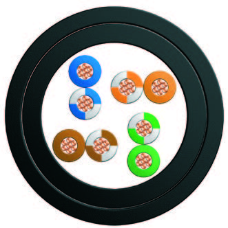
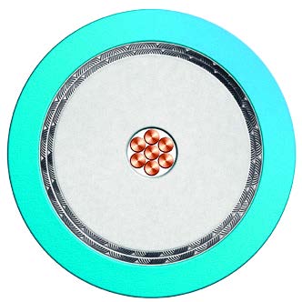
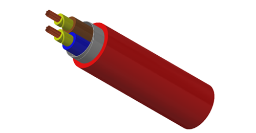
RG6 armoured coaxial cable carries video and other compatible 75 ohm signals on indoor shipboard and marine equipment routes. The cable uses an 18 AWG solid bare copper centre conductor and foam PE dielectric. Foil and tinned copper braid provide the screens; LSZH bedding, separate tinned copper braid armour and an LSZH outer sheath complete the construction. Its nominal overall diameter is 11.2 mm.
IEC 60092-350
IEC 60332-3-22
IEC 60754-1,2
IEC 61034-1,2
NEK 606:2016
Conductors : 18AWG solid bare copper.
Insulation : Foam PE.
Shielding1 : Al/Polyester/Al tape.
Shielding2 : Tinned copper braid.
Bedding : Low smoke and halogen-free polyolefin, coloured black.
Armour : Tinned copper wire braid.
Outer Sheath : Low smoke and halogen-free polyolefin.
| AWG | 18 | |
|---|---|---|
| Nominal Conductor Diameter | mm | 1.0 |
| Impedance | Ω | 75+/-5 |
| Nominal Attenuation@100MHz | dB/100m | 6.9 |
| Nominal Attenuation@200MHz | dB/100m | 9.0 |
| Nominal Attenuation@300MHz | dB/100m | 11.8 |
| Nominal Attenuation@400MHz | dB/100m | 13.1 |
| Nominal Attenuation@500MHz | dB/100m | 15.4 |
| Nominal Attenuation@900MHz | dB/100m | 21.5 |
| Nominal Attenuation@1700MHz | dB/100m | 29.4 |
| Capacitance | pF/m | 53.5 |
| Velocity of Propagation | % | 83 |
| Conductor DCR | Ω/km | 21.4 |
| Shield DCR | Ω/km | 7.5 |
| Inductance | μH/m | 0.32 |
| Time Delay | ns/m | 4 |
Bending Radius : 15×OD
Temperature Range : -30℃ ~ +75℃
| Nominal Inner Conductor Diameter | Nominal Insulation Thickness | Nominal Sheath Thickness | Nominal Overall Diameter | Nominal Weight |
|---|---|---|---|---|
| mm | mm | mm | mm | kg/km |
| 1.0 | 1.8 | 1.2 | 11.2 | 208 |
75±5 ohm impedance and a 1.0 mm nominal centre conductor diameter.
Aluminium/polyester/aluminium tape plus tinned copper braid screening.
Attenuation values at stated frequencies through 1700 MHz for route-loss assessment.
Confirm the required frequency band, connector impedance and allowable signal loss before selecting length. Check connector fit against the complete armoured construction and provide bend space of at least the listed 15 times overall diameter. Where a route includes exposed weather, oil, mud or water contact, include those conditions in the cable specification.
RG11 Armoured Coaxial Cable, 75 Ohm, LSZH Marine Signal Cable
RG59 Armoured Coaxial Cable, 75 Ohm, Foam PE and LSZH Sheath
What is the insulation material?
The centre conductor is insulated with foam PE.
How many screen layers are listed?
There are two: aluminium/polyester/aluminium tape and tinned copper braid. The armour is a further separate layer.
What does the 1700 MHz attenuation row establish?
It gives the nominal cable loss at that frequency. The system's usable frequency range also depends on connectors, equipment and the required signal performance.
Does a general RG6 connector necessarily fit?
Check conductor, dielectric and jacket dimensions, plus the armour termination arrangement, against the connector specification.
Which alternative is useful when comparing route losses?
The related RG11 and RG59 armoured pages provide their own attenuation and dimension data. Compare the same operating frequency and the available cable-entry space.