


The cables are designed for connection between traffic control centers and equipment shelters along the trackside. The cables are specially designed to give good induction protection (R.F= 0.26 at inductive voltage 100V/km) and are suitable for installation in intercity railways electrifi ed at 25KV ac.
SNCF CT 445 / SNCT ST 698G
NF F 55-698
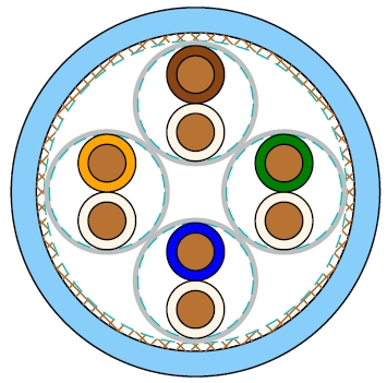
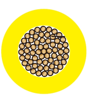
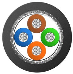
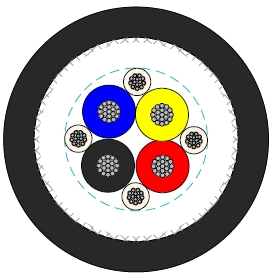
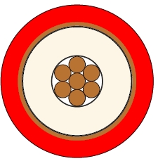
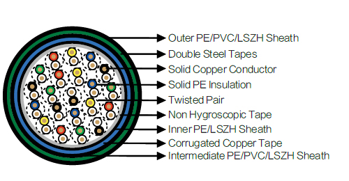
Conductors : Solid annealed copper, 1.0/1.5 mm² nominal cross section area.
Insulation : Solid polyethylene.
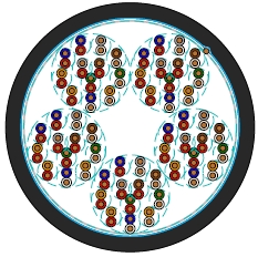
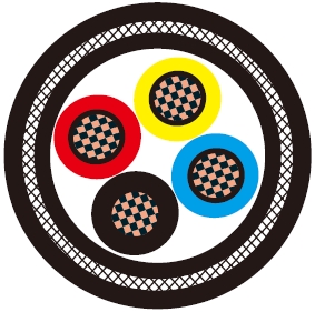
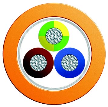
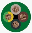
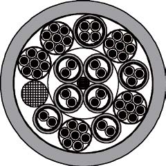
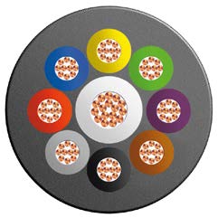
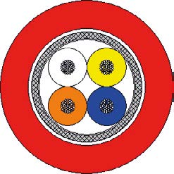
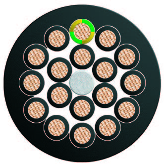
Cabling Element : Each two conductors are twisted together to form a pair.
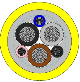
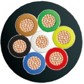
Stranding : Pairs are helically stranded in layers to form the cable core.
Core Wrapping : Plastic tape(s) with overlapping.
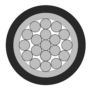
Inner Sheath : PE sheath. LSZH FR option can be offered upon request to NF C 32 070.2.2 (C1).
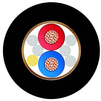
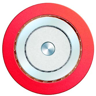
Electrostatic Shield : One corrugated copper tape.
Intermediate Sheath : PE/PVC sheath. LSZH FR option can be offered upon request to NF C 32 070.2.2 (C1).
Electromagnetic Shield : Two helically applied steel tapes of 0.5mm.
Outer Sheath : PE/PVC Sheath. LSZH FR option can be offered upon request to NF C 32 070.2.2 (C1).
Remarks : ZPAU : PE/PVC Sheath; ZPAU-SH : LSZH Sheath.
| Nominal Conductor Diameter | mm | 1.13 | 1.38 |
| Nominal Cross Section Area | mm² | 1.0 | 1.5 |
| Maximum Conductor Resistance (DC) | Ω/km | 18.1 | 12.31 |
| Minimum Insulation Resistance @500 V DC (3mins) | MΩ.km | 5000 | 5000 |
| Maximum Mutual Capacitance @1000Hz (AC) | nF/km | 55 | 55 |
| Maximum Capacitance Unbalance (pair to pair) @800Hz | |||
| 100% cases | pF/500 m | 400 | 400 |
| 90% cases | pF/500 m | 200 | 200 |
| Attenuation @45KHz | dB/km | 2.5 | 2.5 |
| Characteristic Impedance @45KHz | Ω | 120 | 120 |
| Dielectric Strength, conductor to conductor (DC voltage 3secs) | V | 4500 | 4500 |
| Operating Voltage (AC/DC) | V | 450/750 | 450/750 |
| Peak Value (AC) | V | 900 | 900 |
Minimum Bending Radius : 8×OD (static) ; 16×OD (dynamic)
Temperature Range : -40℃ to +70℃ (during operation) ; -20℃ to +50℃ (during installation)
| Inductive Voltage (V/km) Em | 28 | 32 | 37 | 42 | 47 | 50 | 70 | 80 | 100 | 120 | 170 | 225 |
| Reduction Factor @50Hz Rk | 0.75 | 0.70 | 0.60 | 0.50 | 0.40 | 0.35 | 0.30 | 0.28 | 0.26 | 0.25 | 0.24 | 0.25 |
| Cable Code | No. of Pairs | Nominal Sheath Thickness | Nominal Overall Diameter | Nominal Weight | ||
|---|---|---|---|---|---|---|
| Inner | Interm. | Outer | ||||
| mm | mm | mm | mm | kg/km | ||
| 1.13mm Conductor, 2.3mm Insulated Wire | ||||||
| BRAIL ZPAU-2Y2Y(K)2YB2Y-1P1S | 1 | 1.0 | 0.8 | 1.6 | 16.2 | 490 |
| BRAIL ZPAU-2Y2Y(K)2YB2Y-2P1S | 2 | 1.0 | 0.8 | 1.6 | 17.0 | 550 |
| BRAIL ZPAU-2Y2Y(K)2YB2Y-3P1S | 3 | 1.0 | 0.8 | 1.6 | 22.2 | 820 |
| BRAIL ZPAU-2Y2Y(K)2YB2Y-4P1S | 4 | 1.0 | 0.8 | 1.6 | 23.8 | 890 |
| BRAIL ZPAU-2Y2Y(K)2YB2Y-7P1S | 7 | 1.0 | 0.8 | 1.7 | 26.7 | 1080 |
| BRAIL ZPAU-2Y2Y(K)2YB2Y-14P1S | 14 | 1.2 | 0.8 | 1.8 | 32.3 | 1560 |
| BRAIL ZPAU-2Y2Y(K)2YB2Y-21P1S | 21 | 1.2 | 1.1 | 2.0 | 37.2 | 1990 |
| BRAIL ZPAU-2Y2Y(K)2YB2Y-28P1S | 28 | 1.2 | 1.1 | 2.2 | 41.4 | 2380 |
| BRAIL ZPAU-2Y2Y(K)2YB2Y-56P1S | 56 | 1.3 | 1.3 | 2.5 | 52.9 | 3700 |
| 1.38mm Conductor, 2.55mm Insulated Wire | ||||||
| BRAIL ZPAU-2Y2Y(K)2YB2Y-14P1.5S | 14 | 1.2 | 0.8 | 1.8 | 35.0 | 2050 |
| BRAIL ZPAU-2Y2Y(K)2YB2Y-21P1.5S | 21 | 1.2 | 1.1 | 2.0 | 39.5 | 2525 |