


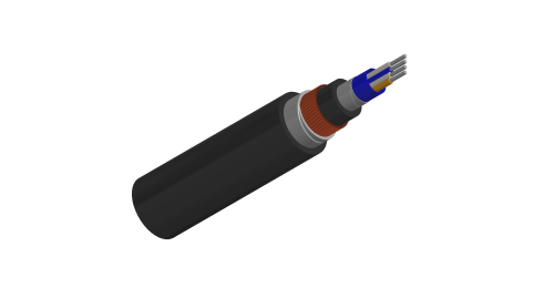
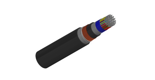
The cables are designed for transmission of signals up to 90 kHz in axle counter train detection systems.
RT/E/PS/00031
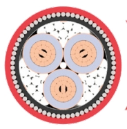
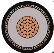
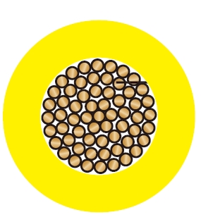
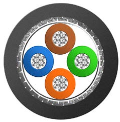
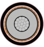
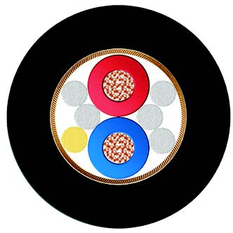
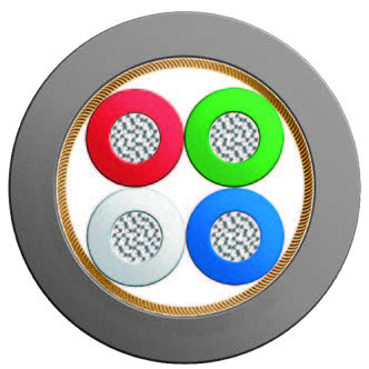
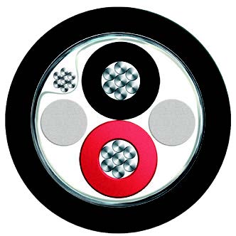
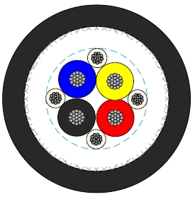
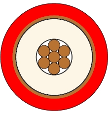
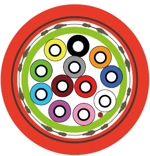
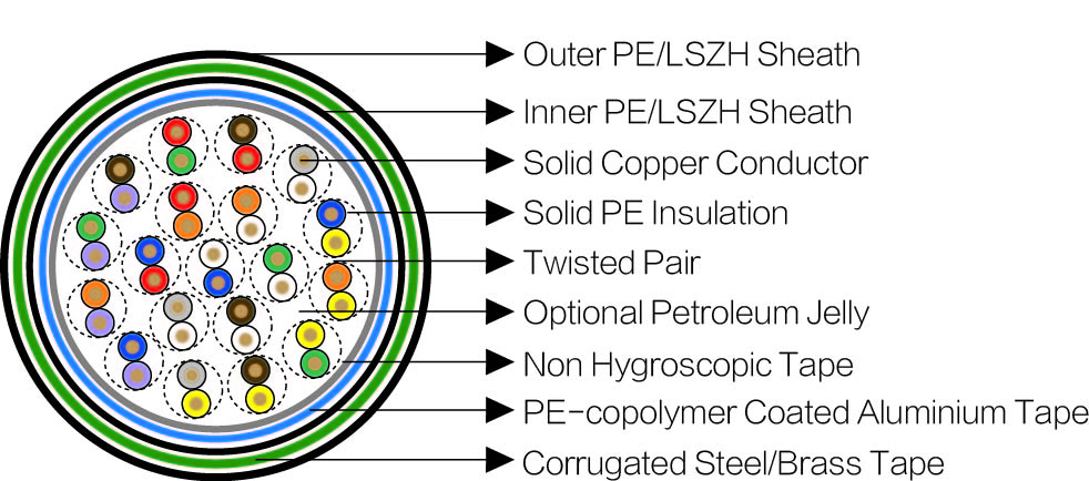
Type CodesConductors: Tinned copper, 0.9/1.4 mm nominal diameter.
Insulation: Solid polyethylene.
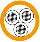
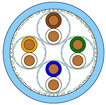
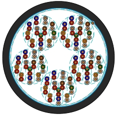
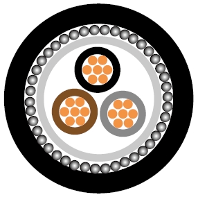
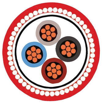
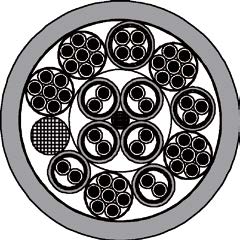
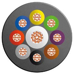
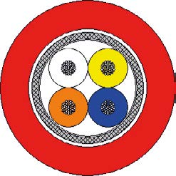
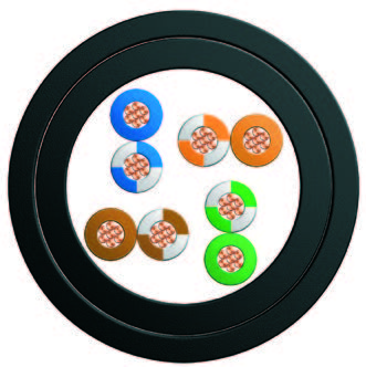
Cabling Element: Two insulated conductors are twisted together to form a pair.
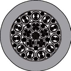
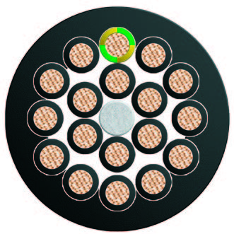
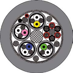
Stranding: Pairs are helically stranded in concentric layers.
Filling: Cable core interstices are filled with a low-permitivity compound. Unfi lled cables option can be offered upon request.
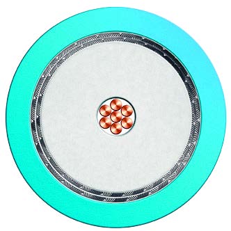
Core Wrapping: Plastic tape(s) with overlapping.
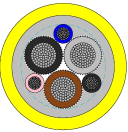
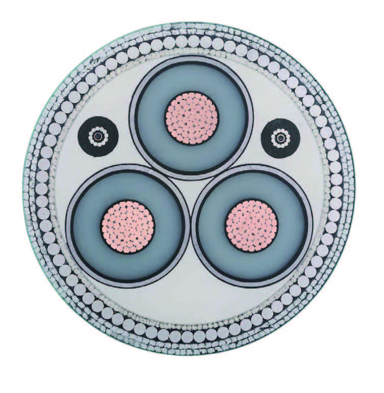
Moisture Barrier: One laminated sheath made of aluminium tape coated with PE Copolymer on at least one side is applied with longitudinally overlap.
Inner Sheath: Polyethylene or LSZH fi re retardant compound.
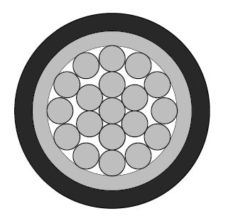
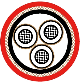
Electrostatic Shield: One layer of helically applied copper wires.
Electromagnetic Shield: Two helically applied steel tapes.
Outer Sheath: Polyethylene or LSZH fi re retardant compound. Ruggedised PE sheath compound can be offered upon request.
F1 class: Non LSZH cables.
F5 class: Unfi lled cables
D type: Unarmoured types
R type: Ruggedised PE sheath
S type: Steel tape armoured types
B type: Brass tape armoured types
E1, E2 & E3 types: 3 different induction protection levels available.
| Nominal Conductor Diameter | mm | 0.9 | 1.4 |
| Nominal Conductor Cross Section | mm | 0.63 | 1.5 |
| Maximum Conductor Resistance | Ω/km | 30.0 | 12.5 |
| Minimum Insulation Resistance @500 V DC (1min) | MΩ.km | 5000 | 5000 |
| Nominal Conductor Capacitance @800Hz/1000Hz (AC) | nF/km | 42+3 | 47+3 |
| Dielectric Strength, conductor to screen (DC voltage 2mins) | V | 3000 | 3000 |
| Maximum Average Attenuation | |||
| @1.0KHz | dB/km | 0.73 | 0.45 |
| @2.4KHz | dB/km | 1.10 | 0.62 |
| @40KHz | dB/km | 2.88 | 1.77 |
| @90KHz | dB/km | 3.70 | 2.41 |
| @1.024MHz | dB/km | 11.2 | 7.45 |
| Minimum Average Near-end Crosstalk | |||
| @1.0KHz | dB/km | 60 | 60 |
| @2.4KHz | dB/km | 60 | 60 |
| @40KHz | dB/km | 50 | 50 |
| @90KHz | dB/km | 50 | 50 |
| @1.024MHz | dB/km | 35 | 35 |
| Maximum Reduction Factor @100V/km,50Hz | |||
| EMI RF 1 (modest level) | 0.65 | 0.65 | |
| EMI RF 2 (medium level) | 0.45 | 0.45 | |
| EMI RF 3 (high level) | 0.20 | 0.20 |
Minimum Bending Radius: 7.5×OD (unarmoured); 10×OD (armoured)
Temperature Range: -30℃ to +60℃ (during operation); -10℃ to +60℃ (during installation)
| Cable Code | Number of Pairs | Nominal Sheath Thickness mm | Nominal Overall Diameter mm | Nominal Weight kg/km | |
|---|---|---|---|---|---|
| Inner | Outer | ||||
| 0.9mm Conductor , 1.8mm Insulated Wire | |||||
| BRAIL RT/F3-S/E3-2Y(F)(L)2YDB2Y-2P0.9 | 2 | 2.2 | 2.4 | 23.4 | 1300 |
| BRAIL RT/F3-S/E3-2Y(F)(L)2YDB2Y-10P0.9 | 10 | 2.2 | 2.4 | 31.8 | 1650 |
| BRAIL RT/F3-S/E3-2Y(F)(L)2YDB2Y-12P0.9 | 12 | 2.2 | 2.4 | 35.0 | 1760 |
| BRAIL RT/F3-S/E3-2Y(F)(L)2YDB2Y-19P0.9 | 19 | 2.2 | 2.4 | 41.4 | 2275 |
| BRAIL RT/F3-S/E3-2Y(F)(L)2YDB2Y-24P0.9 | 24 | 2.2 | 2.4 | 44.0 | 2450 |
| 1.4mm Conductor, 2.7mm Insulated Wire | |||||
| BRAIL RT/F3-S/E3-2Y(F)(L)2YDB2Y-2P1.4 | 2 | 2.2 | 2.4 | 33.6 | 1480 |
| BRAIL RT/F3-S/E3-2Y(F)(L)2YDB2Y-10P1.4 | 10 | 2.2 | 2.4 | 40.2 | 2200 |
| BRAIL RT/F3-S/E3-2Y(F)(L)2YDB2Y-12P1.4 | 12 | 2.2 | 2.4 | 42.2 | 2325 |
| BRAIL RT/F3-S/E3-2Y(F)(L)2YDB2Y-19P1.4 | 19 | 2.2 | 2.4 | 47.5 | 2975 |
| BRAIL RT/F3-S/E3-2Y(F)(L)2YDB2Y-24P1.4 | 24 | 2.2 | 2.4 | 52.5 | 3150 |