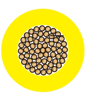
H05 V-U / (H)05 V-U Insulated WiresDesigned for equipment installation in dry indoor environments, production facilities, switchgear and distribution panel interiors, as well as the protective wiring of lighting circuits. Suitable for installation in conduits, or for open or concealed laying under plaster, meeting various fixed wiring needs. This series of wires has a rated voltage of 300/500V, excellent flexibility (bending radius 15x outer diameter) and flame retardant properties (IEC 60332.1), with high insulation resistance, ensuring reliability and safety within an operating temperature range of -5°C to +70°C.
H07 V-U / (H)07 V-U Insulated WiresSuitable for enclosed installation in conduits, under plaster, or on surfaces, making them an ideal choice for internal equipment wiring, distribution panels, and protective lighting circuits. Their rated voltage is as high as 450/750V, capable of withstanding AC voltages up to 1000V or DC voltages up to 750V to ground. These wires are not suitable for direct laying in cable trays, trunking, or ducts. They feature strong voltage withstand capability (test voltage 2500V), high insulation resistance, and remain stable within a static temperature range of -30°C to +90°C, with a short-circuit withstand temperature of up to +160°C.
CEI 20-20/3, CEI 20-35, CEI 20-52, HD 21.3 S3, IEC60332
CE Low Voltage Directive 73/23/EEC and 93/68/EEC, ROHS compliant
Technical Characteristics
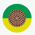
| Solid bare copper single wire |
| Solid to DIN VDE 0295 cl-1 and IEC 60228 cl-1 |
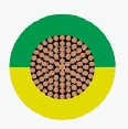
| Special PVC TI1 core insulation |
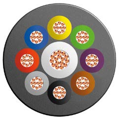
| Cores to VDE-0293 colors on chart |
| H05V-U (20, 18 & 17 AWG) |
| H07V-U (16 AWG and Larger) |
| Working voltage | 300/500v (H05V-U) |
| Working voltage | 450/750v (H07V-U) |
| Test voltage | 2000V(H05V-U)/2500V (H07V-U) |
| Flexing bending radius | 15 x O |
| Static bending radius | 15 x O |
| Flexing temperature | -5oC to +70oC |
| Static temperature | -30oC to +90oC |
| Short circuit temperature | +160oC |
| Flame retardant | IEC 60332.1 |
| Insulation resistance | 10 MΩ x km |
| AWG | No. of Cores x Nominal Cross Sectional Area | Nominal Thickness of Insulation | Nominal Overall Diameter | Nominal Copper Weight | Nominal Weight |
| # x mm^2 | mm | mm | kg/km | kg/km | |
| 20 | 1 x 0.5 | 0.6 | 2.1 | 4.8 | 9 |
| 18 | 1 x 0.75 | 0.6 | 2.2 | 7.2 | 11 |
| 17 | 1 x 1 | 0.6 | 2.4 | 9.6 | 14 |
| 16 | 1 x 1.5 | 0.7 | 2.9 | 14.4 | 21 |
| 14 | 1 x 2.5 | 0.8 | 3.5 | 24.0 | 33 |
| 12 | 1 x 4 | 0.8 | 3.9 | 38.0 | 49 |
| 10 | 1 x 6 | 0.8 | 4.5 | 58.0 | 69 |
| 8 | 1 x 10 | 1.0 | 5.7 | 96.0 | 115 |