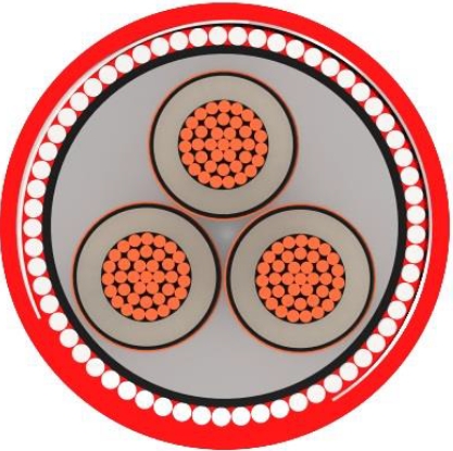
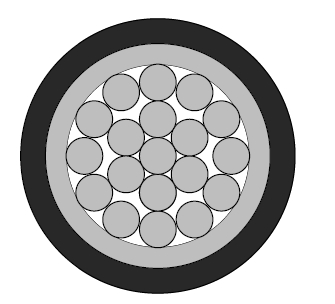
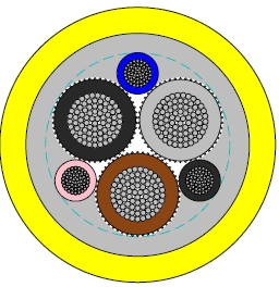
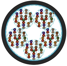
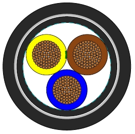
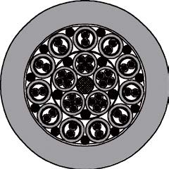
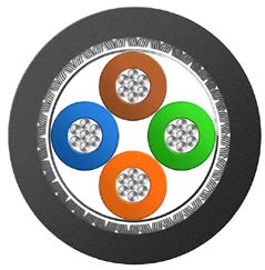
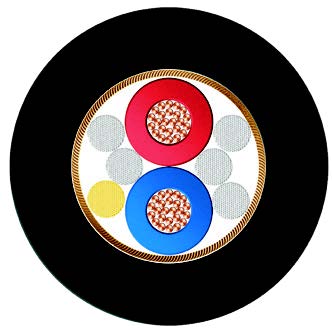
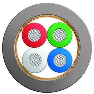
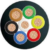
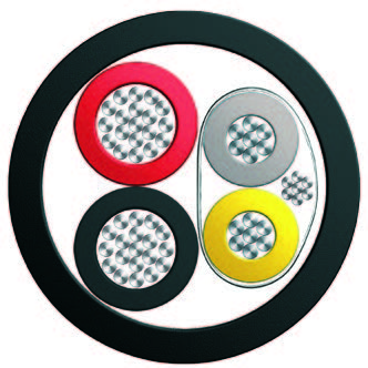
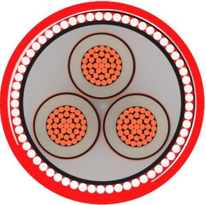
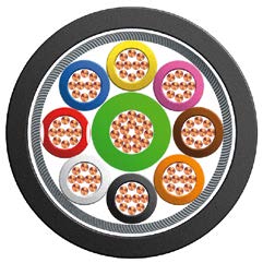
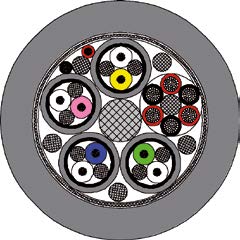
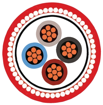
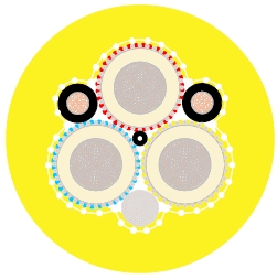
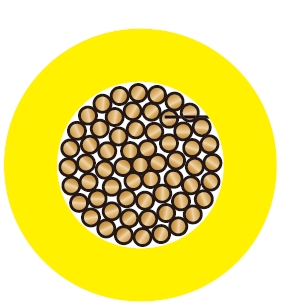
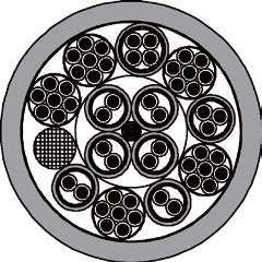
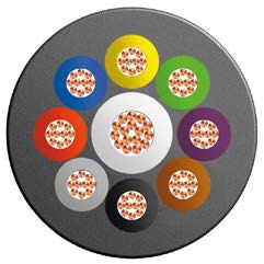
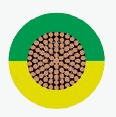
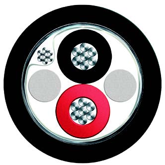
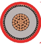
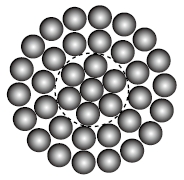
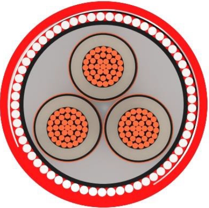
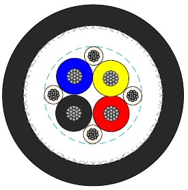
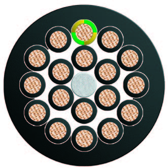
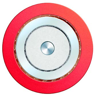
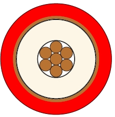
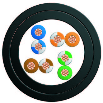
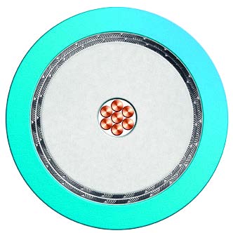
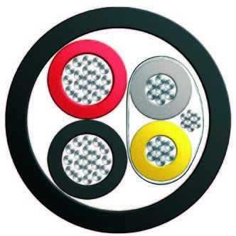
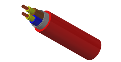
Type B1 and B2 cables connect fixed railway signalling equipment along the route, including connections between equipment locations and signal boxes. Their construction combines class 2 tinned copper conductors, GP4 EPR insulation and an RS2 HDPCP sheath. B1 covers single-core arrangements; B2 covers the twin and multicore arrangements in the dimension schedule. Select the exact row to match the circuit and termination design.
NR/PS/SIG/00005(formerly RT/E/PS/00005)
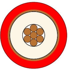
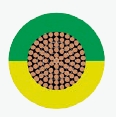
Electrical Characteristics at 20℃Conductors: Tinned stranded copper, class 2 according to IEC 60228 & BS 6360.
Insulation: EPR Type GP4 to BS 7655.
Core Wrapping: Plastic tape(s) with overlapping.
Sheath: HDPCP Type RS2 to BS 7655.
| Nominal Conductor Cross Section | mm | 0.75 | 1.5 | 2.5 | 10.0 | 16.0 | 35.0 | 70.0 | 95 |
| Maximum Conductor DC Resistance | Ω/km | 24.8 | 12.2 | 7.56 | 1.84 | 1.16 | 0.529 | 0.27 | 0.195 |
| Voltage Rating | KV | 0.65/1.1 | |||||||
| Nominal Insulation Thickness | mm | 0.85 | 0.8 | 0.8 | 1.0 | 1.0 | 1.2 | 1.4 | 1.6 |
Minimum Bending Radius: 6×OD (static); 15×OD (dynamic)
Temperature Range: -25℃ to +85℃ (during operation); -10℃ to +85℃ (during installation)
| Cable Code | No. of cores& Nominal Conductor Cross Sectional Area No. ×mm | No. & Nominal Diameter of Strands No/mm | Nominal Sheath Thickness mm | Overall Diameter Min/Max mm | Nominal Weight kg/km |
|---|---|---|---|---|---|
| Type B1 | |||||
| BRAIL B1-3G5G-1G0.75 | 1×0.75 | 7/0.37 | 2.0 | 6.5/8.1 | 28 |
| BRAIL B1-3G5G-1G1.5 | 1×1.5 | 7/0.53 | 2.0 | 6.8/8.5 | 31 |
| BRAIL B1-3G5G-1G2.5 | 1×2.5 | 7/0.67 | 2.0 | 7.2/8.9 | 34 |
| BRAIL B1-3G5G-1G10 | 1×10.0 | 7/1.35 | 2.0 | 9.4/11.8 | 205 |
| BRAIL B1-3G5G-1G35 | 1×35.0 | 19/1.53 | 2.0 | 12.9/16.1 | 495 |
| Type B2 | |||||
| BRAIL B2-3G5G-2G1.5 | 2×1.5 | 7/0.53 | 2.0 | 9.4/12.1 | 135 |
| BRAIL B2-3G5G-2G2.5 | 2×2.5 | 7/0.67 | 2.0 | 10.5/13.1 | 170 |
| BRAIL B2-3G5G-2G10 | 2×10.0 | 7/1.35 | 2.0 | 15.0/18.7 | 443 |
| BRAIL B2-3G5G-2G16 | 2×16.0 | 7/1.70 | 2.0 | 16.7/20.9 | 625 |
| BRAIL B2-3G5G-2G35 | 2×35.0 | 19/1.53 | 2.2 | 22.3/27.8 | 1232 |
| BRAIL B2-3G5G-2G70 | 2×70.0 | 19/2.14 | 2.4 | 28.8/36.0 | 2053 |
| BRAIL B2-3G5G-2G95 | 2×95.0 | 19/2.52 | 2.6 | 33.2/41.5 | 2968 |
| BRAIL B2-3G5G-4G0.75 | 4×0.75 | 7/0.37 | 2.0 | 10.2/12.8 | 140 |
| BRAIL B2-3G5G-7G0.75 | 7×0.75 | 7/0.37 | 2.0 | 11.8/14.7 | 214 |
| BRAIL B2-3G5G-10G0.75 | 10×0.75 | 7/0.37 | 2.0 | 14.4/18.0 | 280 |
| BRAIL B2-3G5G-12G0.75 | 12×0.75 | 7/0.37 | 2.0 | 14.8/18.5 | 321 |
| BRAIL B2-3G5G-19G0.75 | 19×0.75 | 7/0.37 | 2.0 | 17.0/21.3 | 451 |
| BRAIL B2-3G5G-27G0.75 | 27×0.75 | 7/0.37 | 2.0 | 20.1/25.1 | 602 |
| BRAIL B2-3G5G-37G0.75 | 37×0.75 | 7/0.37 | 2.2 | 22.7/28.4 | 799 |
| BRAIL B2-3G5G-48G0.75 | 48×0.75 | 7/0.37 | 2.2 | 25.7/32.2 | 973 |
| BRAIL B2-3G5G-4G1.5 | 4×1.5 | 7/0.53 | 2.0 | 10.9/13.7 | 217 |
| BRAIL B2-3G5G-7G1.5 | 7×1.5 | 7/0.53 | 2.0 | 12.6/15.8 | 296 |
| BRAIL B2-3G5G-10G1.5 | 10×1.5 | 7/0.53 | 2.0 | 15.6/19.4 | 401 |
| BRAIL B2-3G5G-12G1.5 | 12×1.5 | 7/0.53 | 2.0 | 16.0/20.0 | 437 |
| BRAIL B2-3G5G-19G1.5 | 19×1.5 | 7/0.53 | 2.0 | 18.5/23.1 | 615 |
| BRAIL B2-3G5G-27G1.5 | 27×1.5 | 7/0.53 | 2.2 | 22.2/27.8 | 856 |
| BRAIL B2-3G5G-37G1.5 | 37×1.5 | 7/0.53 | 2.2 | 25.1/31.4 | 1126 |
| BRAIL B2-3G5G-48G1.5 | 48×1.5 | 7/0.53 | 2.4 | 28.1/35.1 | 1494 |
| BRAIL B2-3G5G-4G2.5 | 4×2.5 | 7/0.67 | 2.0 | 11.9/14.8 | 260 |
| BRAIL B2-3G5G-7G2.5 | 7×2.5 | 7/0.67 | 2.0 | 13.8/17.2 | 370 |
| BRAIL B2-3G5G-10G2.5 | 10×2.5 | 7/0.67 | 2.0 | 17.1/21.3 | 520 |
| BRAIL B2-3G5G-12G2.5 | 12×2.5 | 7/0.67 | 2.0 | 17.6/22.0 | 599 |
| BRAIL B2-3G5G-19G2.5 | 19×2.5 | 7/0.67 | 2.0 | 20.4/25.5 | 835 |
| BRAIL B2-3G5G-27G2.5 | 27×2.5 | 7/0.67 | 2.2 | 24.6/30.7 | 1232 |
| BRAIL B2-3G5G-37G2.5 | 37×2.5 | 7/0.67 | 2.4 | 27.8/34.7 | 1623 |
| BRAIL B2-3G5G-48G2.5 | 48×2.5 | 7/0.67 | 2.6 | 31.2/39.0 | 2032 |
| BRAIL B2-3G5G-6P0.75S | 6×2×0.75 | 7/0.37 | 2.0 | 19.7/24.6 | 372 |
Class 2 tinned copper conductors with EPR insulation.
HDPCP outer sheath for the Type B construction.
A common 0.65/1.1 kV voltage entry with size-specific resistance and dimension data.
Specify conductor size and core arrangement together. Check the circuit voltage, resistance allowance and terminal capacity, then use the listed overall-diameter range for glands and route space. Where a project calls for an LSZH outer sheath, compare Type D and its specified insulation option. Plan screen or armour requirements separately from the sheath choice.
What separates B1 from B2?
B1 is the single-core family. B2 includes the twin and multicore arrangements identified in the dimension table.
Is the Type B sheath LSZH?
This construction uses HDPCP. Type D provides a related LSZH-sheathed option.
Are the conductors class 5?
The Type B construction specifies class 2 tinned stranded copper. Type C uses class 5 conductors.
Does this construction include a screen?
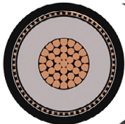
The listed layers are conductor, EPR insulation, wrapping and HDPCP sheath. A screened circuit should use a construction selected for that requirement.
Which dimensions matter at cable entries?
Use the minimum and maximum overall diameter for the exact order code, together with the gland's permitted sealing range.